36 TRAX ZP-AJ01E AJ0383DE
5 OPERATING INSTRUCTIONS
If OLTC
Important
Do not use autostop when testing OLTC.
OLTC measurements must be performed
by winding (see global settings).
1] When reading is stable, press
The measurement and the result is captured
and displayed for the actual row/tap.
Measurement will continue on the next table
row (next tap position).
Note Do not stop generating until last tap is tested.
2] Operate tap changer.
A] If a discontinuity occurs (brake before
make), TRAX will automatically stop the
test, discharge the winding and report
fail in the continuity column.
The discontinuity is reported on the row/
tap that the switch transition is going TO,
i.e a transition discountinuity when going
from tap 5 to 6 will be reported on the
row for tap 6.
B] If continuity is OK, TRAX will start meas-
ure resistance for the actual tap on the
active row.
Wait for stable reading and press
TRAX will continue to measure next posi-
tion.
3] Repeat from step 2.
Continue until last tap.
4] Stop measurement (generator) and capture
data when the reading is stable.
5] Reconnect cables and perform test on next
phase.
Winding variation will be displayed when all phases
are measured.
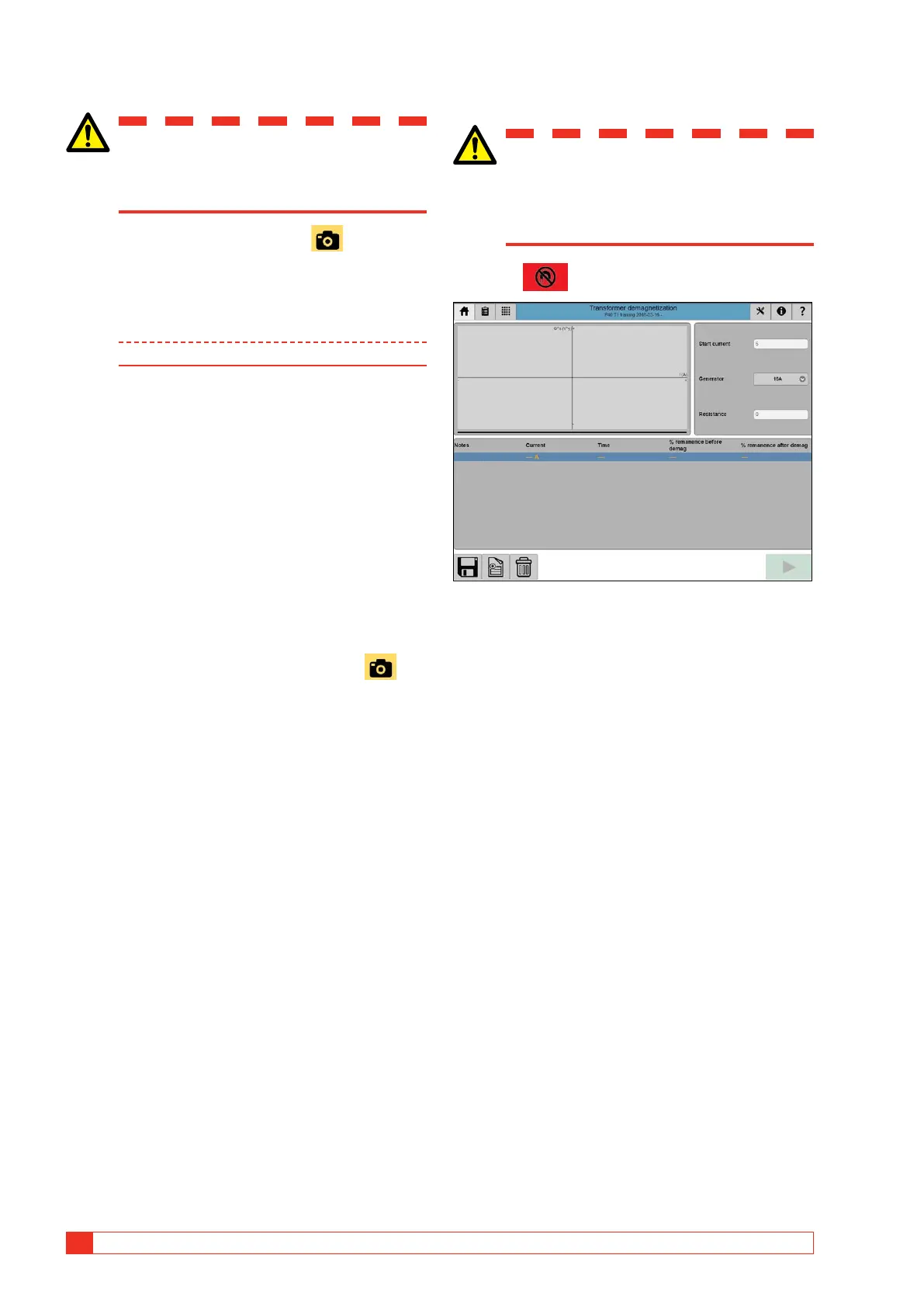
5.6 Demagnetization
Important
Read and comply with the safety instruc-
tions “2 Safety” on page 8.
Always comply with local safety regula-
tions.
1] Press
Demagnetization is recommended before performing
any tests on the transformer and in particular before
excitation current and/or SFRA.
Demagnetization with TRAX is performed by injecting
an alternating and decreasing DC voltage / current to
magnetize the core in two directions. Starting current
is normally selected as about the same as the last per-
formed winding resistance test and should be above
the DC saturation level of the actual winding (typically
1 % of rated winding current). Demagnetization is
normally done on the HV side of the transformer and
on the connection with the lowest excitation current
(the mid-leg for a YN configuration). For configura-
tions with no neutral, demagnetization connection is
terminal-terminal.
The adaptive algorithm for the demagnetization pro-
cess is based on measuring and reducing Vs (voltage
* time). This implies that the voltage measurement R1
MUST be connected during demagnetization.

 Loading...