FX-2000 Series Installation and Operation Manual
9
Chassis Installation
1. Group the incoming wires through the top of the enclosure to prepare it for wiring the modules. Do not run the
wires in-between the modules since it could cause a short circuit.
2. Use a wire tie to group wires for easy identification and neatness.
3. Be sure to connect a solid earth ground (from building system ground / to a cold water pipe) to the chassis
earth ground mounting lug, and to connect the earth ground wire lugs from the main chassis to the ground
screw on the backbox.
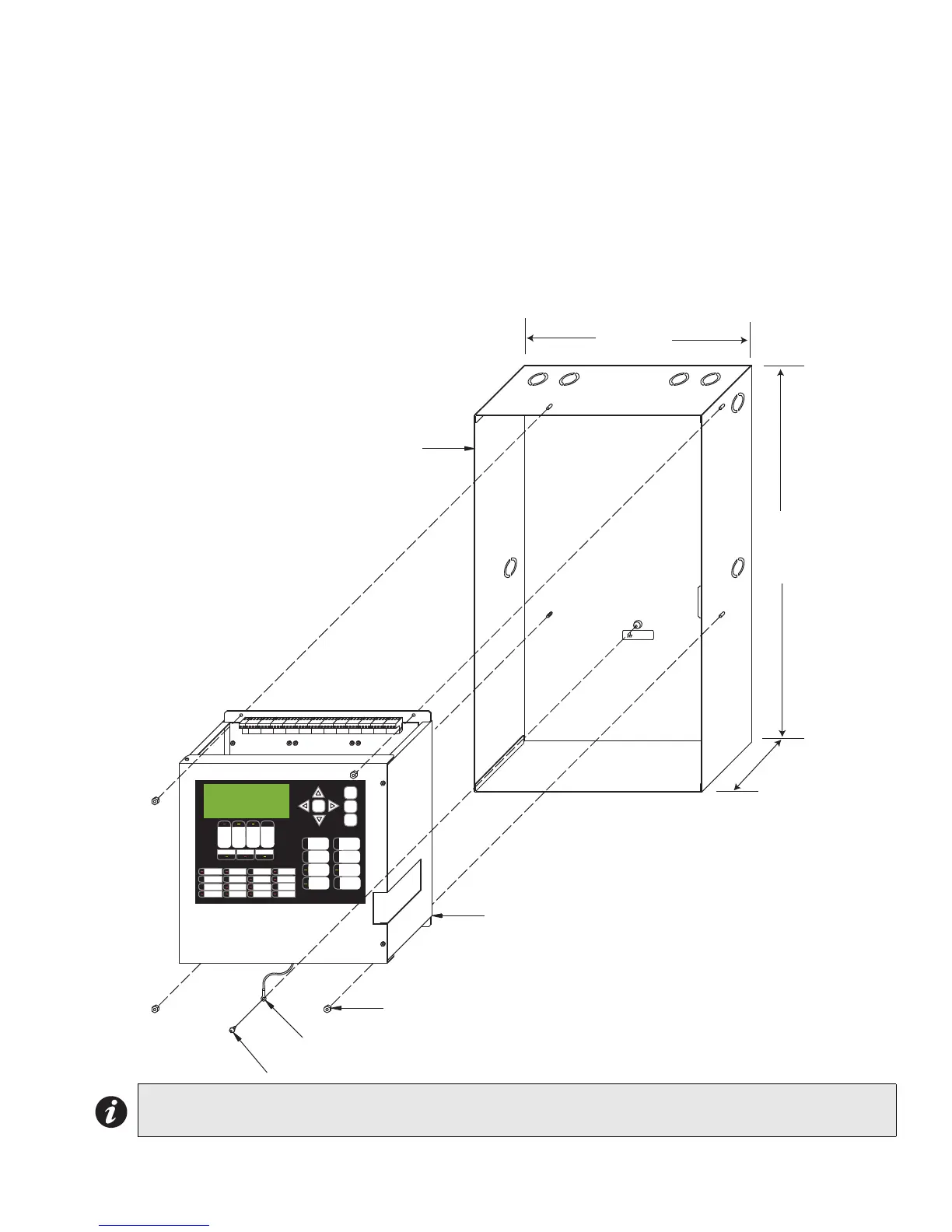
4. Mount chassis FX-2003-6 or FX-2003-12 into backbox BBX-1024 using the supplied hexnuts as shown in
Figure 4 below.
Figure 4: Chassis Installation into BBX-1024
Note: Leave bottom of box conduit free for batteries.
GROUND
CHASSIS
ALARM
QUEUE
SUPV.
QUEUE
TROUBLE
QUEUE
MONITOR
QUEUE
A.C. ON
PRE-ALARM
GND FAU LT
Mircom FX-2000
Fire Alarm Control Pane l
Nor mal Co nd ition
Decemb er 31, 1999
SIGN A L
SILEN C E
GENERAL
ALARM
ACKNOW-
LEDGE
FIRE
DRILL
SYSTEM
RESET
LAMP
TEST
ENTER
MENU
CANCEL
INFO
14 1/2”
26”
4 1/2”
BACKBOX
MAIN CHASSIS
FX-2003-6 or FX-2003-12
#8-32 HEXNUTS (4)
EARTH GROUND LUG
#8 X 1/4” TYPE ‘B’ SCREW

 Loading...


