Module Mounting Locations
12
Module Mounting Locations
The FX-2003-6/12 or FX-2017-12A Main Chassis come pre-assembled with a main panel, display components and
boards. Install adder modules of different types as shown in the diagrams on the following pages.
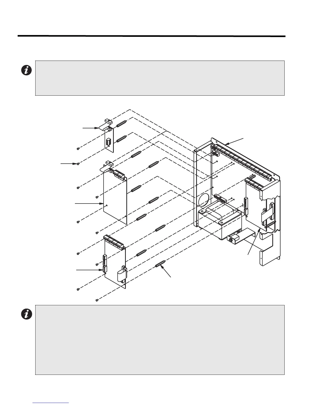
Figure 7: Module Mounting Locations View #1
Notes: For many adder modules to enable communication from the main module to all of the adder
modules, it is necessary to add a continuity jumper on the last adder module in a chain (see the
appropriate module settings section to verify the location of the continuity jumper on a particular
circuit adder module). Only the last circuit adder module should have a jumper plug on its continuity
jumper; all others must be left without a jumper plug.
Notes:
1. Front plate is not shown.
2. Reserved for PR-300 or UDACT-300A.
3. Other circuit adder modules may be:
• DM-1008A Detection Circuit Adder Module
• SGM-1004A Signal Circuit Adder Module
• RM-1008A Relay Circuit Adder Module
• ALC-198S Loop Adder Module
• ALC-396S Loop Adder Module
• ALC-H16 Hardwire Loop Controller Module
MODEL: FX-2003-X
MAIN CHASSIS
(SEE NOTE 1)
SCREW
#6-32 x 1 1/2"
M/F HEX SPACER
(SEE NOTE 2)
(SEE NOTE 2)
(SEE NOTE 3)
OTHER CIRCUIT ADDER
#6-32 x 1 1/4"
(SEE NOTE 3)
MODULE
PR-300 CITY TIE MODULE
OTHER CIRCUIT ADDER
UDACT-300A
DIALLER MODULE

 Loading...


