FX-2000 Series Installation and Operation Manual
17
Main Fire Alarm Super Module (MD-757 Part of “S” Version Main Chassis)
This super main board does not have any addressable loops on it. For an addressable loop, adder boards are
required.
JW1 Jumper is removed if a PR-300 or UDACT-300A is installed.
JW2 to JW4 Jumpers are Factory Set and should not be changed.
P3 Black RS-485 Connector connects to the Adder Loop ALC-198S, ALC-396S or ALC-H16 if used
(Address Loops 2, 3, etc.)
P4 Connector for PR-300 Module or UDACT-300A.
NO HARDWIRE CIRCUIT ADDER MODULES ARE CONNECTED TO THIS MAIN FIRE ALARM SUPER
MODULE
P8 Power Connector for Adder Modules.
P7 White BDM Connector for Factory Use.
P9 RS-232C for Printer or “CRT” Monitor.
P10,11 Factory connection to Bridge Rectifier.
P12,13 Connection to 24 VDC Battery. Observe Polarity.
P14 Connector for Display Module.
F1 20 Amp slow blow non-replaceable fuse.
TO CONFIGURE THE FIRE ALARM PANEL USE THE RS-485 CONNECTOR P4 OF THE LAST ADDER LOOP
CONTROLLER MODULE INSTALLED.
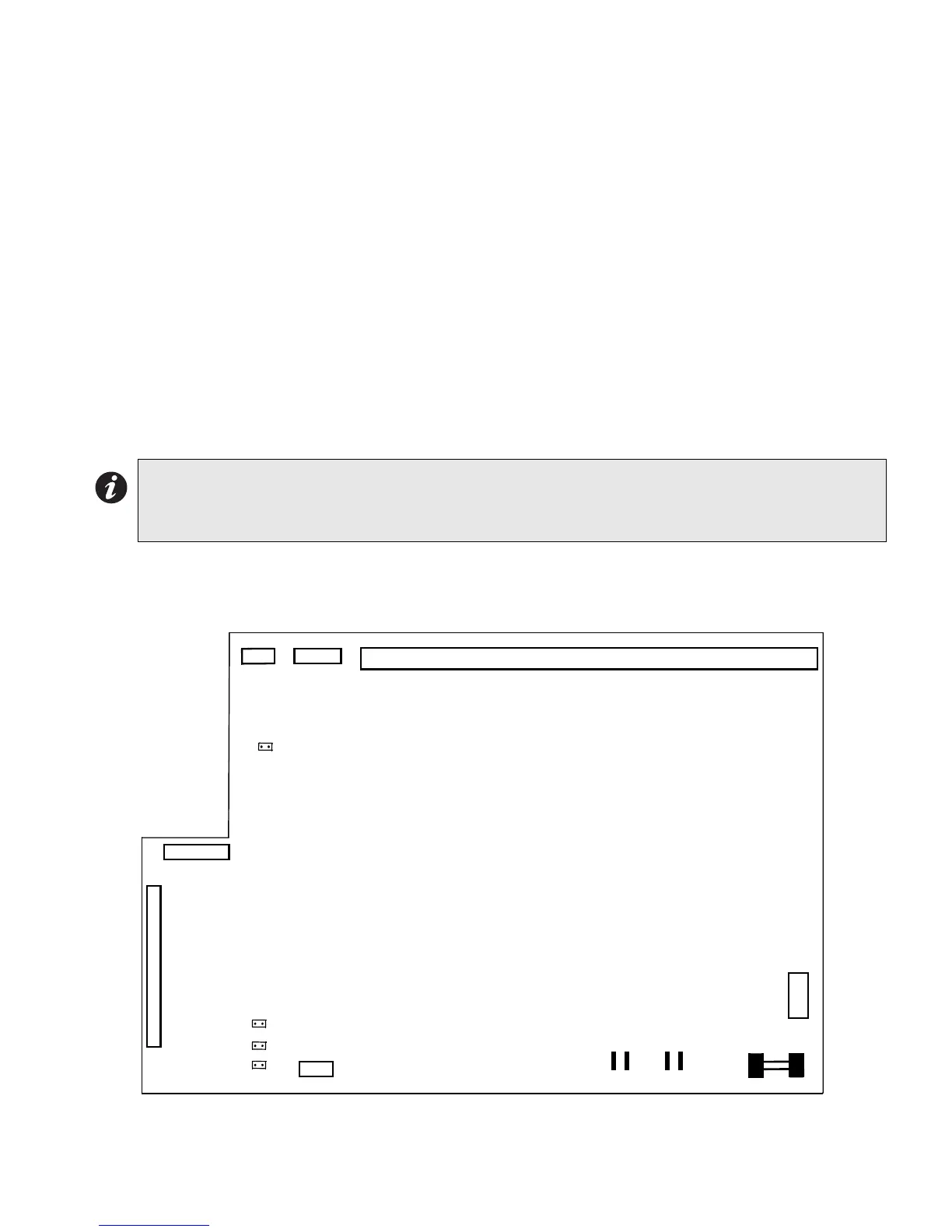
Figure 10: Main Fire Alarm Super Module (MD-757 Part of “S” Version Main Chassis)
Note: To enable communication from the Main Module to all of the Adder Modules, it is necessary to add a Continuity
Jumper on the last Adder Module in a chain (see the appropriate Module Settings section to verify the location
of the Continuity Jumper on a particular Circuit Adder Module). Only the last circuit adder module should have
a jumper plug on its continuity jumper; all others must be left without a jumper plug.
MAIN FIRE ALARM SUPER BOARD
FIELD WIRING TERMINALS
P9
P8
F1
P10 P11 P12 P13
+BDG- +BAT-
P7
JW1
P4
JW4
P14
P3
JW2
JW3

 Loading...


