M
Matthew PaceAug 2, 2025
What to do if Mircom Control Panel shows Battery Trouble?
- BBelinda ArcherAug 2, 2025
If your Mircom Control Panel indicates a Battery Trouble and the voltage is low (below 20.4V), replace the batteries as soon as possible.

What to do if Mircom Control Panel shows Battery Trouble?
If your Mircom Control Panel indicates a Battery Trouble and the voltage is low (below 20.4V), replace the batteries as soon as possible.
What to do if Mircom Control Panel has Ground Fault?
If you are experiencing a Ground Fault with your Mircom Control Panel, check for any external wiring that may be touching the chassis or any other earth ground connection.
How to fix Circuit Trouble on Mircom Control Panel?
To address a Circuit Trouble issue on your Mircom Control Panel, check for open wiring on the affected circuit loop. Also, ensure that the circuit disconnect switch is in the ON or CLOSED position.
| Type | Fire Alarm Control Panel |
|---|---|
| Maximum devices per loop | 99 |
| Power Supply | 120 VAC, 60 Hz |
| Battery Backup | 24VDC, 7Ah |
| Programming | Via PC |
| SLC Loops | 1 |
| Operating Temperature | 0°C to 49°C (32°F to 120°F) |
| Compatibility | Mircom devices |
| Display | LCD |
Overview of the FX-2000 Intelligent Analog Fire Alarm Control Panel.
Key features and capabilities of the FX-2000 system.
Defines terms "circuits" and "zones" for fire alarm systems.
Explains different wiring configurations for initiating and indicating circuits.
Details various chassis models for the FX-2000 system.
Lists and describes modules that expand system functionality.
Describes auxiliary modules like PR-300 and UDACT-300A.
Lists available enclosure models for mounting system components.
Describes flush trim rings for specific enclosure models.
Lists and describes remote annunciator panels for the FX-2000.
Details battery specifications and types used with the system.
Lists optional accessories for the FX-2000 system.
Installation instructions and dimensions for BBX-1024 enclosure.
Installation instructions and dimensions for BBX-1072A enclosure.
Installation instructions and dimensions for BB-5008 enclosure.
Step-by-step guide for installing the chassis into the backbox.
Instructions for installing FX-2017-12A chassis into BBX-1072A backbox.
Installation instructions and dimensions for BB-5014 backbox.
Diagram showing where to mount various modules within the main chassis.
Mounting locations for display and adder modules in the compact chassis.
Mounting locations for display and adder modules in the mid-size chassis.
Mounting locations for display and adder modules in the large chassis.
Mounting locations for display and adder modules in the expander chassis.
Lists various adder modules available for the FX-2000 system.
Lists various display modules available for the FX-2000 system.
Details jumpers, connectors, and fuse for the main fire alarm module.
Details the super main board and its components for "S" version chassis.
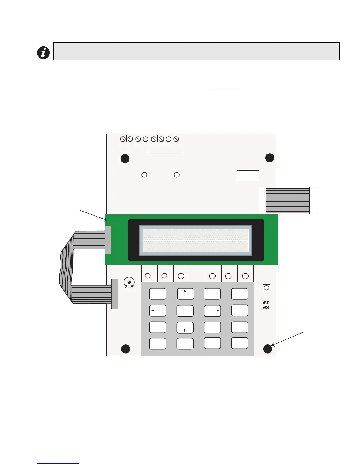
Describes the main display module, its controls, and indicators.
Describes the zone display module and its interface.
Details the programmable input switches module and its layout.
Describes the fan damper control display modules.
Explains the operation of the FDX-008/FDX-008KI fan damper control module.
Details the FDX-008KI fan damper control display module with keyswitch.
Details the DM-1008A hardwire detection adder module.
Details the SGM-1004A hardwire signal adder module.
Describes the components and LEDs of the SGM-1004A module.
Explains the three modes of operation for the SGM-1004A module.
Details jumpers for enabling bell cut operation on the SGM-1004A.
Details jumpers for connecting isolators on the SGM-1004A.
Details the RM-1008A hardwire relay adder module.
Details the PR-300 module for polarity reversal and city tie connections.
Describes the UDACT-300A main board and its layout.
Details terminal connections for the UDACT-300A main board.
Describes the ALC-198S single intelligent analog loop controller module.
Diagram of the ALC-198S module showing ports and jumpers.
Describes the ALC-396S dual intelligent analog loop controller module.
Diagram of the ALC-396S module showing ports and DIP switches.
Describes the ALC-H16 hardwire loop controller module.
Diagram of the ALC-H16 module showing ports and DIP switches.
Details terminal connections for the main fire alarm module.
Continued diagram of main fire alarm module terminal connections.
Wiring diagrams for analog loops.
Shows Class B wiring for analog loops.
Shows Style 7 wiring for analog loops with isolators.
Shows Style 6 wiring for analog loops.
Wiring diagram for single loop Class B connections.
Wiring diagram for single loop Style 7 connections.
Wiring diagram for single loop Style 6 connections.
Details terminal connections for the DM-1008A detection module.
Details terminal connections for the SGM-1004A signal module.
Details terminal connections for the RM-1008A relay module.
Wiring diagram for the PR-300 polarity reversal and city tie module.
Details telephone line wiring for the UDACT-300A module.
Details power supply connections and ratings for main chassis models.
Provides wiring tables for initiating and indicating circuits.
Specifies maximum wire runs for analog loops based on wire gauge.
Pre-power up checks and precautions for system installation.
Steps for powering up the system and initial status indicators.
Common error messages and their solutions for the FX-2000 panel.
Explains the function of common LEDs and the buzzer on the panel.
Describes the LCD display and the function of control buttons.
Details the functions of System Reset, Signal Silence, Fire Drill, and other buttons.
Describes how the system behaves in single-stage alarm mode.
Describes system behavior in two-stage alarm and general alarm modes.
Explains how to configure and operate the pre-signal mode.
Defines and categorizes different types of initiating circuits.
Categorizes indicating circuits (Silenceable, Non-Silenceable, Coded, Strobe).
Describes various evacuation codes used by the system.
Specifications for the FX-2003-6 main chassis.
Specifications for the FX-2017[S]-12A main chassis.
Specifications for the ALC-198S module.
Specifications for the ALC-396S module.
Specifications for the ALC-H16 loop controller module.
Specifications for the SGM-1004A signal adder module.
Specifications for the RM-1008A relay adder module.
Specifications for the PR-300 module.
Specifications for the FDX-008 and FDX-008KI modules.
Specifications for the DM-1008A detection adder module.
Specifications for the RAX-1048[TZ] annunciator chassis.
Specifications for the UDACT-300A digital communicator module.
Specifications for the IPS-2424 programmable input switches module.
System model, type, service, and applicable standards.
Lists compatible addressable loop modules for UL.
Lists compatible two-wire smoke detectors for UL.
Lists compatible four-wire smoke detectors for UL.
Lists compatible signalling devices for UL.
Lists compatible addressable loop modules for ULC.
Lists compatible hardwire smoke detectors for ULC.
Lists compatible hardwire smoke detectors for ULC (continued).
Lists compatible synchronized modules and strobes.
Details intervals for ULI retard, reset, restart, and confirmation.
Provides tables for calculating power supply and battery requirements.
Vital warnings for installers and end-users regarding system failures.
Important information for installers to convey to system users.
Discusses various reasons for potential system failures.
Mircom's warranty disclaimer regarding software.
Warnings about the limitations of alarm notification appliances.
Warnings about potential issues with telephone lines.
Discusses limitations related to response time in emergencies.
Acknowledges the possibility of component failure.
Emphasizes the importance of regular testing and maintenance.
States that an alarm system is not a substitute for insurance.
Details the two-year limited warranty for materials and workmanship.
Outlines warranty terms for international customers.
Lists conditions that will void the product warranty.
Explains the process for obtaining warranty service.
States the warranty is entire and in lieu of all others.
Procedures and conditions for out-of-warranty repairs.


