Module Settings
32
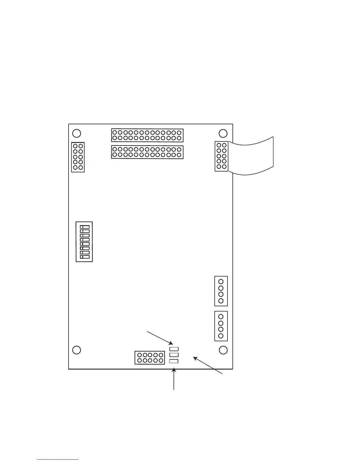
Figure 24: ALC-H16 Hardwire Loop Controller Module
Mount the ALC-H16 Hardwire Loop Controller module as shown on on page 13 and ECX-0012 Expander Chassis
for FX-2009-12 on page 14. The module may be mounted over the main chassis board or in any position that an
adder module is mounted.
There is no wiring at the ALC-H16 Hardwire Loop Controller module, but there is wiring at the 16 standard
conventional adder modules. For conventional hardwire circuit wiring refer to Figure 34: Hardwire Detection Module
(DM-1008A) Terminal Connections on page 41, Figure 35: Hardwire Signal Module Terminal Connections on
page 42, and Figure 36: Hardwire Relay Module Terminal Connections on page 43 for the specific module you are
wiring.
RS-485
CABLE
RS-485
ADDRESS
DIP
SW I TCH
BDM PORT
POWER
CABLE
(OUT)
POWER
CABLE
(IN)
P4
P12
P13
P3
P2
P1
ON
1
8
JW3
JW1
JW2
JW2 - THE
JUMPER IS
KEPT HERE
FOR
NORMAL
OPERATION
JW1 - PINS ARE
SH O RTED
MOMENTARILY TO
RESET
H ARDWARE
JW3 - JUMPER
FROM JW2 IS
PLACED HERE TO
BYPA SS
WATCHDOG FOR
FACT ORY
DOWNLOADING
USING BDM
DIP SWITCHES ARE FOR
THIS BOARD=S ADDRESS.
SW-1 IS THE LEAST
SIGNIFICANT DIGIT (BINARY).
ACTIVE POSITION IS OFF.
P12 IS USED TO CONNECT SECOND GROUP OF 8 ADDER MODULES
P13 IS USED TO CONNECT FIRST GROUP OF 8 ADDER MODULES

 Loading...


