Module Settings
16
Module Settings
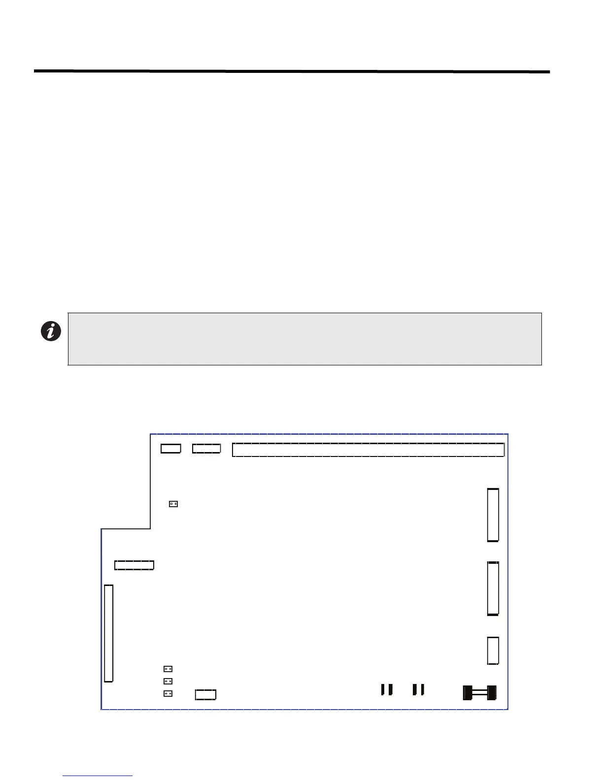
Main Fire Alarm Modules (MD-764 Part of Main Chassis)
JW1: Remove jumper if a PR-300 or UDACT-300A is installed.
JW2 to JW4: Jumpers are factory set and should not be changed.
P3: Black RS-485 Connector connects to the Adder Loop ALC-198S, ALC-396S or ALC-H16 if used
(Address Loops 3, 4, etc).
P4: Connector for PR-300 module or UDACT-300A.
P6: Connector for first eight conventional hardwire circuit adder modules (Loop 0).
P5: Connector for next eight conventional hardwire circuit adder modules (Loop1).
P7: White BDM Connector for factory use only.
P8: Power Connector for Adder Modules.
P9: RS-232C for printer or CRT monitor.
P10, P11: Factory connection to bridge rectifier.
P12,13: Connection to 24VDC battery. Observe correct polarity.
P14: Connector for display module.
F1: 20 Amp slow blow non-replaceable fuse.
TO CONFIGURE THE FIRE ALARM PANEL USE THE RS-485 CONNECTOR P4 OF THE LAST ADDER LOOP
CONTROLLER MODULE INSTALLED.
Figure 9: Main Fire Alarm Board
Note: To enable communication from the Main Module to all of the Adder Modules, it is necessary to add a Continuity
Jumper on the last Adder Module in a chain (see the appropriate Module Settings section to verify the location
of the Continuity Jumper on a particular Circuit Adder Module). Only the last circuit adder module should have
a jumper plug on its continuity jumper; all others must be left without a jumper plug.
MAIN FIRE ALARM SUPER BOARD
FIELD WIRING TERMINALS
P9
P8
F1
P10 P11 P12 P13
+BDG- +BAT-
P7
JW1
P4
JW4
P14
P3
JW2
JW3
P5
P6

 Loading...


