Indicators, Controls, and Operation
50
Indicators, Controls, and Operation
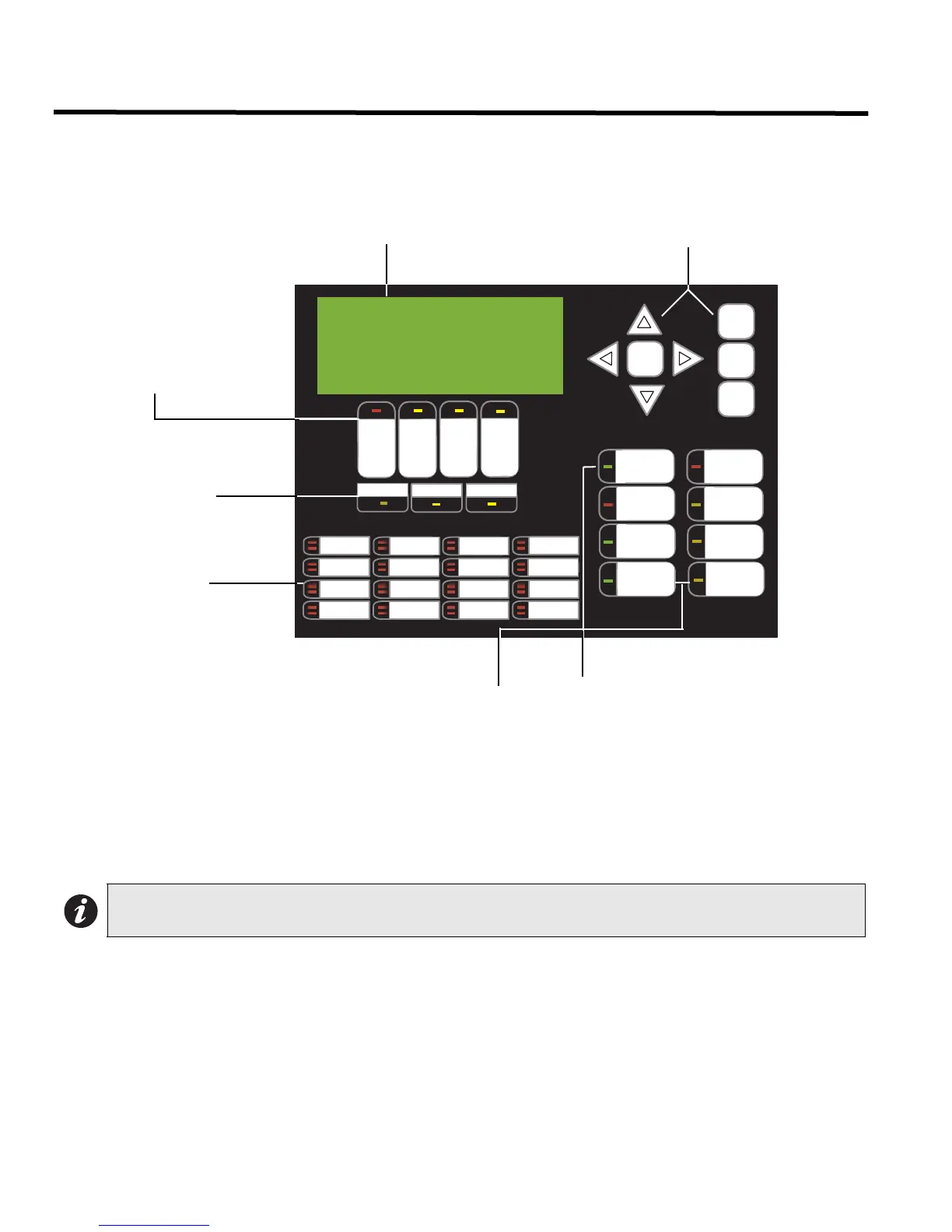
Refer to Figure 37 below for LED indicators, control buttons, and switches locations.
Figure 40: Indicators and Control Location
LED indicators are amber (trouble or supervisory), red (alarm), or green (AC On), and may illuminate continuously
(steady) or at one of two flash rates:
• Fast Flash: 120 flashes per minute, 50% duty cycle
• Trouble Flash: 20 flashes per minute, 50% duty cycle
Paper Labels for Buttons and Indicators
Buttons and indicators are supplied with paper labels. These labels slide into the plastic label templates on the face
of the panel. Paper labels allow for easy English / French selection and custom-printed zone information.
Note: The General Alarm LED and pushbutton, and the Acknowledge LED and pushbutton, are active only
on a system configured for “Two Stage.”
ALARM
QUEUE
SU PV.
QUEUE
TROUBLE
QUEUE
MONITOR
QUEUE
A.C. ON
CPU FAULT
GND FAULT
SI G N A L
SI L EN CE
GENERA L
ALARM
ACKNOW-
LEDGE
FIRE
DRILL
SYST EM
RESET
LAMP
TEST
EN T ER
MENU
CA NCEL
INFO
LED 0
LED 1
LED 2
LED 3
LED 4
LED 5
LED 6
LED 7
LED 8
LED 9
LED 10
LED 11
LED 12
LED 13
LED 14
LED 15
CO NF I GU RA BL E
SWITCH/ LED 3
CO NF I GU RA BL E
SWITCH/ LED 7
Mircom FX-2000
Fire Alarm Control Panel
Normal Condition
April 25, 2003
LCD Display - four lines,
20 characters per line
Cursor buttons,
ENTER, MENU, CANCEL, INFO
Queue controls and
indicators for Alarm,
Supervisory, Trouble,
and Monitor
Indicators for AC On,
CPU Fault, and Ground
Fault (GND FAULT)
Controls & Indicators for Signal
Silence, General, Alarm,
Acknowledge, Fire Drill, System
Reset, Lamp Test
16 configurable
bi-coloured zone
indicators and 16
trouble indicators
Two configurable
switches & amber LEDs

 Loading...


