FX-2000 Series Installation and Operation Manual
33
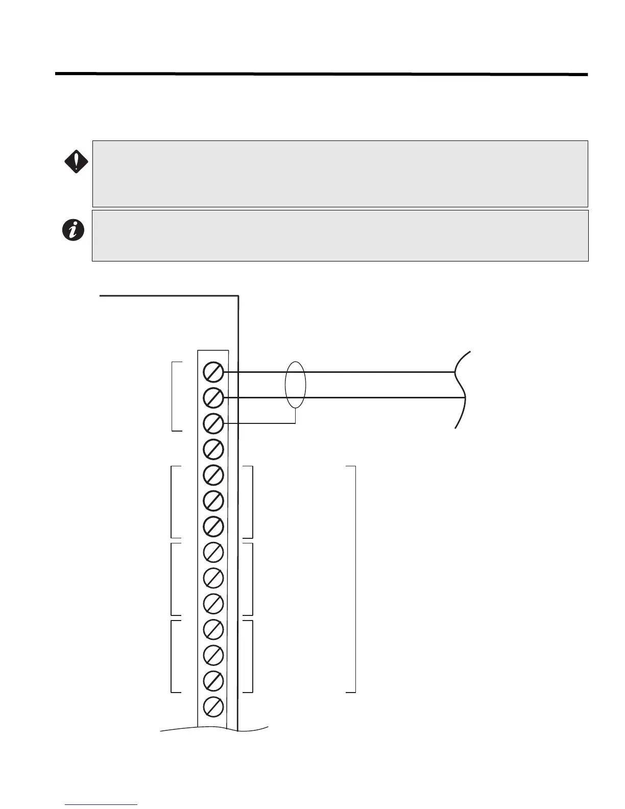
Field Wiring
Main Fire Alarm Module Terminal Connections
Wire devices to terminals as shown in Figure 26 below. See on page 13 for details, Appendix A: Specifications on
page 59, and Appendix B: Compatible Devices on page 61 for compatible devices.
Figure 25: Main Fire Alarm Module Terminal Connections
ATTENTION: Do not exceed power supply ratings:
• Main Chassis FX-2003-6: total current for indicating circuits is 5A max.
• Main Chassis FX-2003-12 or FX-2017-12A: total current for indicating circuits is 10A max.
• Main Chassis FX-2009-12: total current for indicating circuits is 10A max.
Notes:
• The terminal blocks are "depluggable" for ease of wiring.
• All power limited circuits must use type FPL, FPLR, or FPLP power limited cable.
COM
-
RS485
NO
NC
COM
TROUBLE
NO
NC
COM
SIG GND
or COM(-)
NO
NC
ALARM
USE TWISTED SHIELDED PAIR.
22 AWG UP TO 2000 FT.
20 AWG UP TO 4000 FT.
SUPV.
+
S
RS-485 INTERFACE TO
ANNUNCIATORS AND
OTHER DEVICES
(POWER LIMITED)
NOT USED
MUST BE
CONNECTED TO A
LISTED POWER
LIMITED SOURCE
OF SUPPLY
COMMON TROUBLE
CONTACTS
28 VDC, 1 AMP
RESISTIVE LOAD
AUXILIARY COMMON
SUPERVISORY
CONTACTS
28 VDC, 1 AMP
RESISTIVE LOAD
AUXILIARY COMMON
ALARM CONTACTS
28 VDC, 1 AMP
RESISTIVE LOAD
S

 Loading...


