Module Settings
22
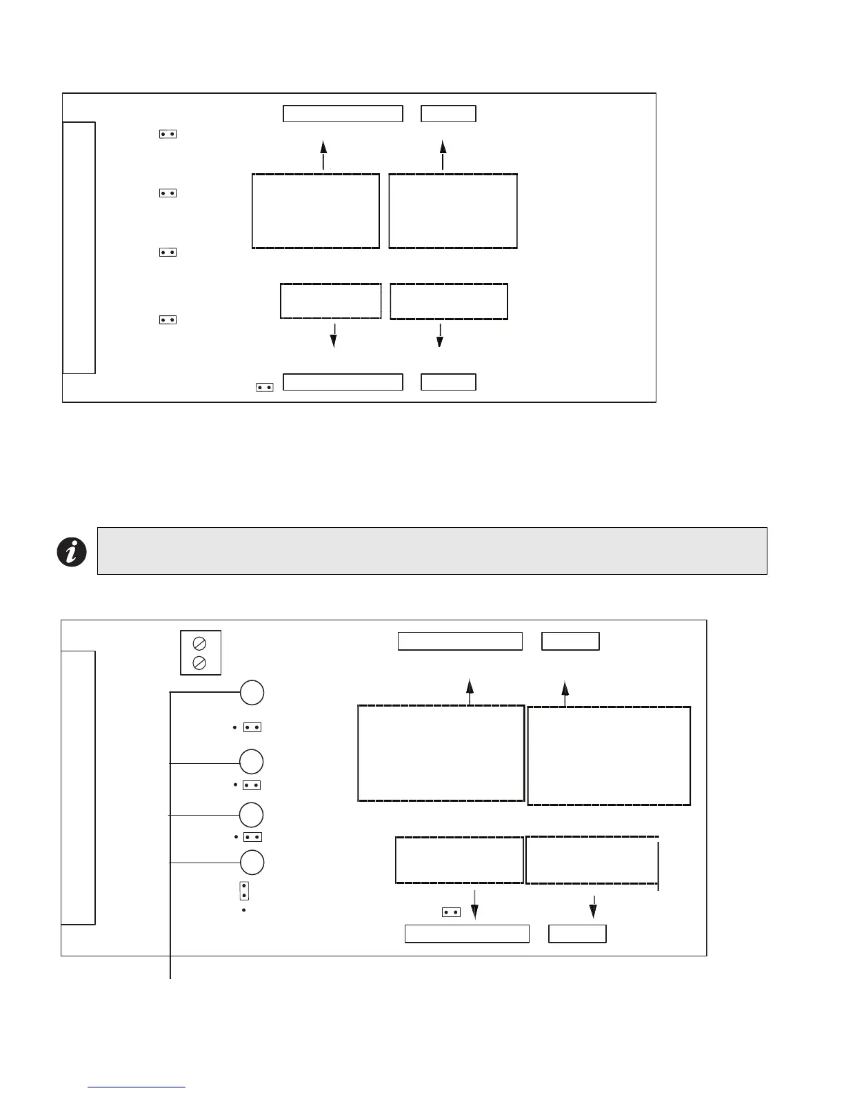
Figure 17: Hardwire Detection Adder Module (DM-1008A)
JW1: Install jumper for Class A (Style D) operation of initiating circuits 1 and 2.
JW2: Install jumper for Class A (Style D) operation of initiating circuits 3 and 4.
JW3: Install jumper for Class A (Style D) operation of initiating circuits 5 and 6.
JW4: Install jumper for Class A (Style D) operation of initiating circuits 7 and 8.
JW5: Remove continuity jumper if there are any more adder modules installed.
Figure 18: Hardwire Signal Adder Module (SGM-1004A)
Note: For Class A (Style D) operation the FX-2000 must be configured as Class A via the configuration
program.
P1
P3
P4
FI ELD WI RING TERM I NALS
P2
JW 5
JW 4
JW 3
JW 2
JW 1
Data cable to P6 or P5 of
main fire alarm module or to
P12 or P13 of hardwire
loop controller module, or
previous adder module
Power connector to P8 of
main fire alarm module,
or to P2 of hardwire loop
controller module, or to
previous adder module
Data connector for
next adder module
Power connector for
next adder module
P1
P3
P4
FIELD WIRING TERMINALS
P2
JW1
JW5
JW4
JW3
JW2
J11
1 2 3
GREEN SIGNAL LEDs
ZONE 4
ZONE 3
ZONE 2
ZONE 1
Power connector to P8 of
main fire alarm module,
or to P2 of loop controller
module, or to previous
adder module
Data cable to P6 or P5 of
main fire alarm module or to
P12 or P13 of loop controller
module, previous adder
module
Data connector for
next adder module
Power connector for
next adder module

 Loading...


