Module Settings
18
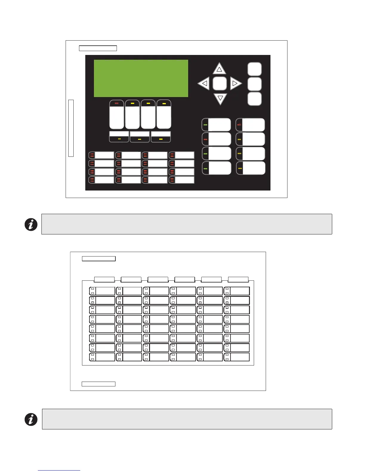
Figure 11: Main Display Module (Part of Main Chassis)
P1: Cable connects to P14 of main fire alarm module. P2: Connection to P1 of any adder display module if used.
Figure 12: Zone Display Module (RAX-1048 or RAX-1048TZ)
P1: Cable connects to P2 of previous display module. P2: Cable connects to P1 of next display module.
Note: The main display module comes with slide-in paper labels including both English and French slide-
ins, and laser printer-compatible blanks for zone labelling.
Note: The zone display module comes with laser printer-compatible slide-in paper labels for zone labelling.
P1
ALARM
QUEUE
SU PV.
QUEUE
TROUBLE
QUEUE
MONITOR
QUEUE
A.C. ON
CPU FAULT
GND FAULT
SI G N A L
SI L EN CE
GENERA L
ALARM
ACKNOW-
LEDGE
FIRE
DRILL
SYST EM
RESET
LAMP
TEST
EN T ER
MENU
CA NCEL
INFO
LED 0
LED 1
LED 2
LED 3
LED 4
LED 5
LED 6
LED 7
LED 8
LED 9
LED 10
LED 11
LED 12
LED 13
LED 14
LED 15
CO NF I GU RA BL E
SWITCH/ LED 3
CO NF I GU RA BL E
SWITCH/ LED 7
Mircom FX-2000
Fire Alarm Control Panel
Normal Condition
April 25, 2003

 Loading...


