FX-2000 Series Installation and Operation Manual
21
Before mounting the FDX-008KI module, if a keyswitch is to be connected, wire the keyswitch to terminals at TS1
as shown in Figure 17: FDX-008KI Fan Damper Control Display Module below.
Mount the FDX-008 and FDX-008KI Fan Damper Control Display modules in any position on the front part of the
FX-2000 chassis as shown in the FX-2000 Manual.
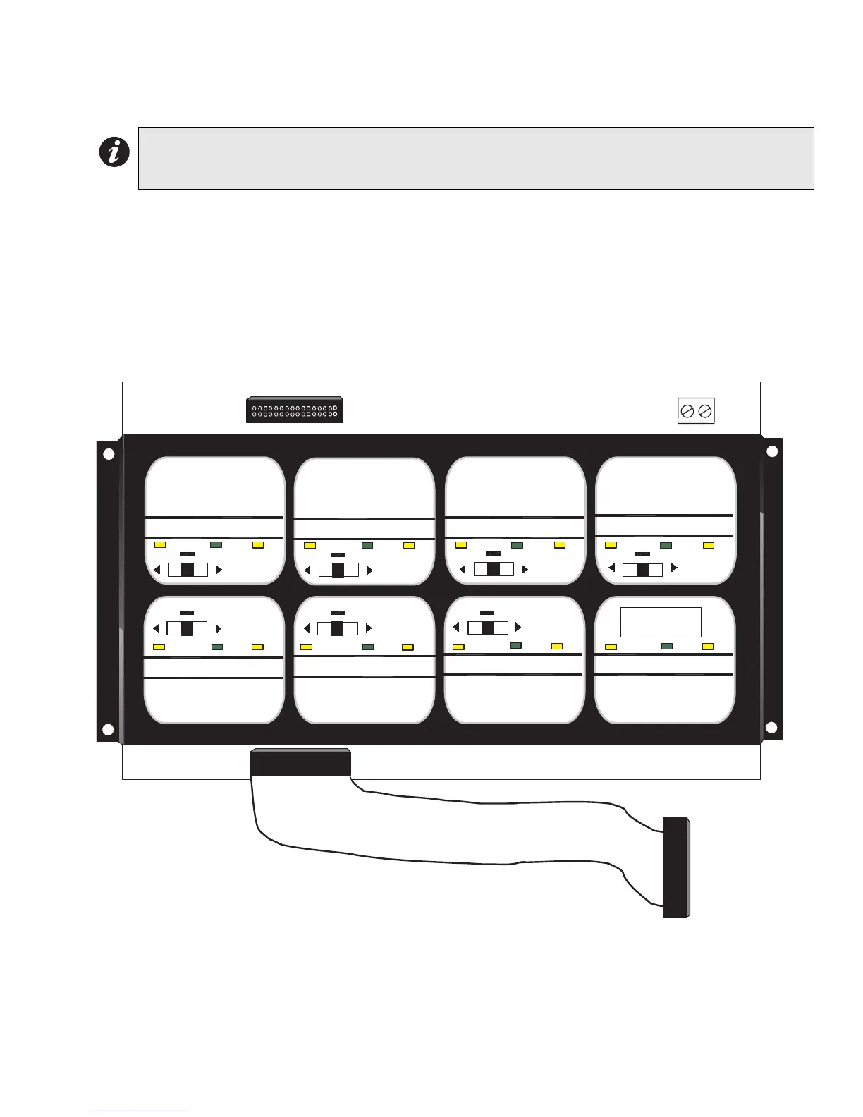
Figure 16: FDX-008KI Fan Damper Control Display Module
Note: There are also terminals located behind TS1 on the other side of the board for the convenience of
wiring the keyswitch. The last fan damper zone in the bottom right position of the FDX-008KI is
controlled by the keyswitch.
OFF AUTO ON TROUBLE
OFF AUTO ON TROUBLE
OFF AUTO ON TROUBLE
OFF AUTO ON TROUBLE
OFF AUTO ON TROUBLE
OFF AUTO ON TROUBLE
OFF AUTO ON TROUBLE
OFF AUTO ON TROUBLE OFF AUTO ON TROUBLE
TS1
P2
TERMINALS AT TS1 ARE WIRED TO A KEYSWITCH.
NOTE: IF FAN DAMPER MODULE IS MOUNTED TO
THE DOOR USE TERMINALS LOCATED AT THE
BACK OF THIS BOARD, BEHIND TS1.
P1
KEYSWITCH
CONTROLLED
CONNECTS TO
PREVIOUS DISPLAY
MODULE P2

 Loading...


