Module Settings
24
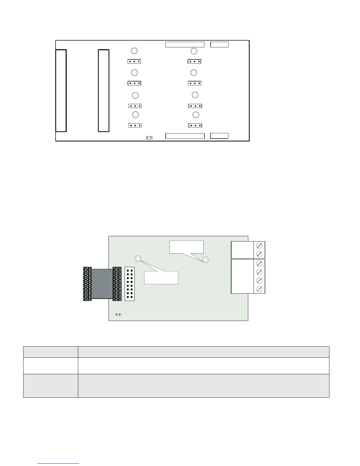
Figure 19: Hardwire Relay Adder Module (RM-1008A)
P2: Data cable to P6 or P5 of main fire alarm module, or to P12 or P13 of Hardwire loop controller module, or to previous adder
module.
P1: Data connector for next adder module.
P4: Power connector to P8 of main fire alarm module, or to P2 of Hardwire loop controller module, or to previous adder module.
P3: Power connector for next adder module.
JW1: Remove continuity jumper if there are any more adder modules installed. If this is the last module installed, leave JW1 on.
JP1-JP8: Move jumpers from pins 1 and 2 to 2 and 3 to connect relay commons between two or more relays.
Polarity Reversal and City Tie Module (Model PR-300)
Figure 20: Polarity reversal and city tie module
The following hardware configuration must be performed before installing the PR-300.
Table 1: PR-300 jumper settings
The Alarm Transmit signal to the PR-300 can be programmed to turn OFF when signal silence is active. This allows
the City Tie Box to be manually reset. On subsequent alarms the silenceable signals will resound and the City Tie
Box will be retriggered. Please refer to the Configurator for more information.
The Trouble Transmit signal to the PR-300 can be programmed to delay AC power fail. Please refer to the
P1 Cable connects to P5 on the FX-2000 Main Fire Alarm Board
P2
P2 is for connecting the UDACT-300A if both PR-300 and UDACT-300A are installed on the
FX-2000.
JW4
If the PR-300 is used this is the last module jumper. JW1 on the main board should be
removed and JW4 on the PR-300 should be set. If both PR-300 and UDACT-300A are
installed, then JW1 on the main board and JW4 on the PR-300 should be removed.
P1
P3
P4
FIELD WIRING TERMINALS
P2
JW1
FIELD WIRING TERMINALS
3 2 1
3 2 1
3 2 1
3 2 1
3 2 1
3 2 1
3 2 1
3 2 1
JP1
JP2
JP3
JP4
JP5
JP6
JP7
JP8
I1
I2
I3
I4
I5
I6
I7
I8
POLARITY
REVERSAL
ALARM
POLARITY
REVERSAL
SUPV
CITY
TIE
+ | - + | - + | -
JW4
P1 P2
Mounting hole for
#6-32 screws
Mounting hole for
#6-32 screws

 Loading...


