Module Settings
26
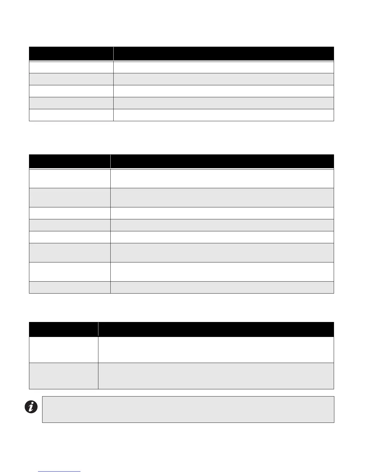
Table 2: Cable Connectors and Miscellaneous
The following table lists all the LEDs located on the UDACT-300A board and states the function of each LED.
Table 3: UDACT-300A List of LEDs and their Functions.
See the UDACT-300A Installation and Operation Manual (LT-888) for more information.
Cable Connector Function
P1 Ribbon Cable for connecting to P4 of FX-2000 FACP.
P2 RS-232C/RS-485 Connection for computer configuration.
U18 Connector for CFG-300 Configuration Tool
Lamp Test button Press and hold this button to test all the UDACT-300A LEDs
UR1 Potentiometer This potentiometer is for adjustment of the CFG-300 LCD contrast.
LEDs Function
Relay Line 1
Located below Line 1 terminal block. When Line 1 relay is energized, this green
LED will illuminate
Relay Line 2
Located below Line 2 terminal block. When Line 2 relay is energized, this green
LED will illuminate.
RS-485 Status LED for communication, will flash when RS-485 communication is active.
Common Trouble Steady amber for any troubles on the Fire Alarm panel or UDACT-300A.
CPU Fail Steady amber for any on board CPU trouble.
Telephone Line 1
Telephone status indicator LED; Red when the line is in use, Amber when there is
a line trouble.
Telephone Line 2
Telephone status indicator LED; Red when the line is in use, Amber when there is
a line trouble.
Power ON Green LED is ON steady when power is supplied to the board.
The following table lists the user jumpers available on the UDACT-300A and their functions.
Table 4: UDACT-300A List of Jumpers for Operation and Configuration
Jumper Number Jumper Function
JW1
Normally open. Place jumper here and power down the UDACT-300A by disconnecting
P1 or power down the fire alarm panel (AC and Batteries), then power back to revert to
default passcode. After reset, remove the jumper. Leave normally open.
JW2
Normally open to BLOCK remote configuration via modem, PC with a UIMA converter
module or using the LCD and keypad at the UDACT-300A. Place jumper here to
ALLOW any type of configuration. Remove jumper once configuration is complete.
Note: Can be installed with the PR-300 City Tie but not in the same location. If using this configuration the
PR-300 must be installed on the left and it is recommended that the UDACT-300A be installed in the
middle, although it can be installed on the right if needed.

 Loading...


