α
2 Simple Application Controllers
DCF77 Radio Clock 10
ENG-49
ENG
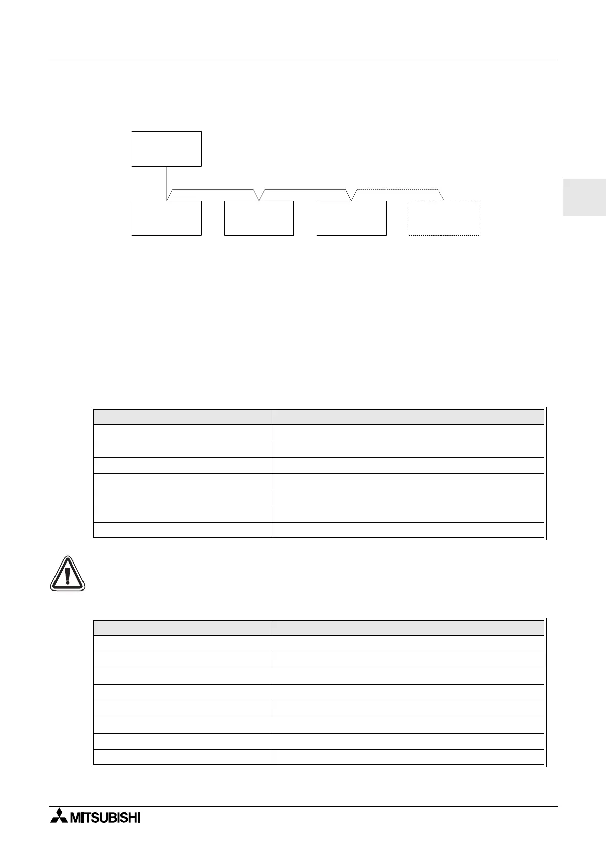
10.2 System Configuration
Figure 10.1:
The
α2 series must use a Theben DCF77 antenna and at least one Theben device to power
the antenna. The
α2 series internal decoding will only recognise a Theben DCF77 signal.
The extra Theben device must power the antenna with 12V DC, only a Theben power supply
can be used to provide the required power and signal line.
A maximum of 10
α2 series main units can be connected in one configuration.
10.3 Specifications
For general specifications please refer to Chapter 2.
Caution
• To avoid interference from external signals, do not use the Theben DCF77 antenna in
TV, PC or telecommunications areas.
Table 10.2: Theben DCF77 Antenna
Item Content
Part Name DCF 77 Antenna 907 0 243
Ambient Temperature -20 - 70°C
Protection IP 54
Reception Threshold 100μV/m
Reception Area approx. 1000km from Frankfurt
Connection cable length max. 200m
Polarity none
Table 10.3: Theben Power-pack
Item Content
Part Name Power pack NT DCF 77 907 0 182
Operating Voltage 230V AC~ +/-10%
Nominal frequency 50-60Hz
Internal consumption max. 3VA
Power-line length max. 200m individually conducted two-core power line
Capacity 10 units
Protection class II acc. to EN 60335
Protection IP20 acc. to EN 60529
DCF 77
Antenna*
NT DCF 77
Power-pack*
α
2 Series
α
2 Series
α
2 Series
* Manufactured by Theben AG

 Loading...


