α
2 Simple Application Controllers
AL2-2PT-ADP 12
ENG-71
ENG
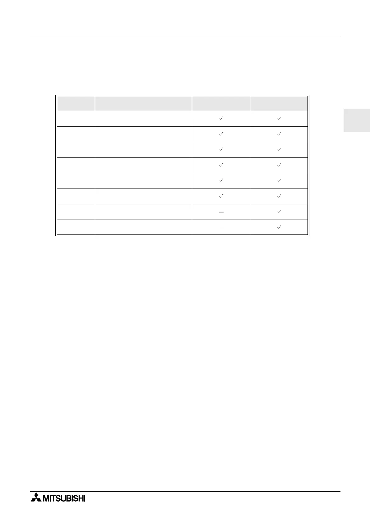
12.4.7 Applicable Error checks
In the event that the input voltage is greater than 11 V or equal to 0V the following system flags
will be set.
- If the flags in the table above are activated, check that:
• a sensor is connected
• there is not a break in the sensor connection
• the temperature is not greater than the specified limit
• that power is being supplied to the AL2-2PT-ADP.
- If the “Error” message appears instead of “OK” while offset/gain calibration, check that.
• The power is being supplied to the AL2-2PT-ADP.
• The AL2-2PT-ADP is connected to α2 correctly.
• The input, which connects the AL2-2PT-ADP is selected for calibration.
• The AL2-2PT-ADP inputs L1- and l1- are shortened.
• The jumper on is placed either on the “-50°C” position or the “200°C” position.
• The calibration menu entry related to the jumper position is selected (“-50°C” or “200°C”).
Table 12.8:
AL2-10MR-D
AL2-14MR-D
AL2-24MR-D
M17
0: Normal
1: Defect at I01
M18
0: Normal
1: Defect at I02
M19
0: Normal
1: Defect at I03
M20
0: Normal
1: Defect at I04
M21
0: Normal
1: Defect at I05
M22
0: Normal
1: Defect at I06
M23
0: Normal
1: Defect at I07
M24
0: Normal
1: Defect at I08

 Loading...


