C-7
2 Specifications
2.2 Power Supply Specifications
FX
3U
/FX
3UC
Series PLC User's Manual - Analog Control Edition
FX3U-4AD-ADP (4-channel analog Input)
A
Common Items
B
FX
3UC
-4AD
C
FX
3U
-4AD-ADP
D
FX
3U
-4DA-ADP
E
FX
3U
-4AD-PT
-ADP
F
FX
3U
-4AD-TC
-ADP
G
PID Instruction
(FNC 88)
2.2 Power Supply Specifications
2.3 Performance Specifications
Item Specifications
A/D conversion circuit
driving power
24V DC +20%-15%, 40mA
(It is necessary to connect the 24V DC power supply to the terminal block.)
Interface driving power
5V DC, 15mA
(Since the internal power is supplied from the FX Series main unit, it is not
necessary to supply the power.)
Item
Specifications
Voltage input Current input
Analog input
range
0V to 10V DC
(Input resistance: 194 kΩ)
4mA to 20mA DC
(Input resistance: 250 Ω)
Maximum
absolute input
-0.5V, +15V -2mA, +30mA
Digital output 12 bits, binary 11 bits, binary
Resolution 2.5mV (10V/4000) 10µA (16mA/1600)
Total accuracy
• ±0.5% (±50mV) for full scale of 10V (when
ambient temperature is 25°C ± 5°C)
• ±1.0% (±100mV) for full scale of 10V (when
ambient temperature is 0°C to 55°C)
• ±0.5% (±80µA) for full scale of 16mA (when
ambient temperature is 25°C ± 5°C)
• ±1.0% (±160µA) for full scale of 16mA (when
ambient temperature is 0°C to 55°C)
A/D conversion
time
200 µs (The data will be updated at every scan time.)
→ For a detailed description of data update, refer to Section 2.4.
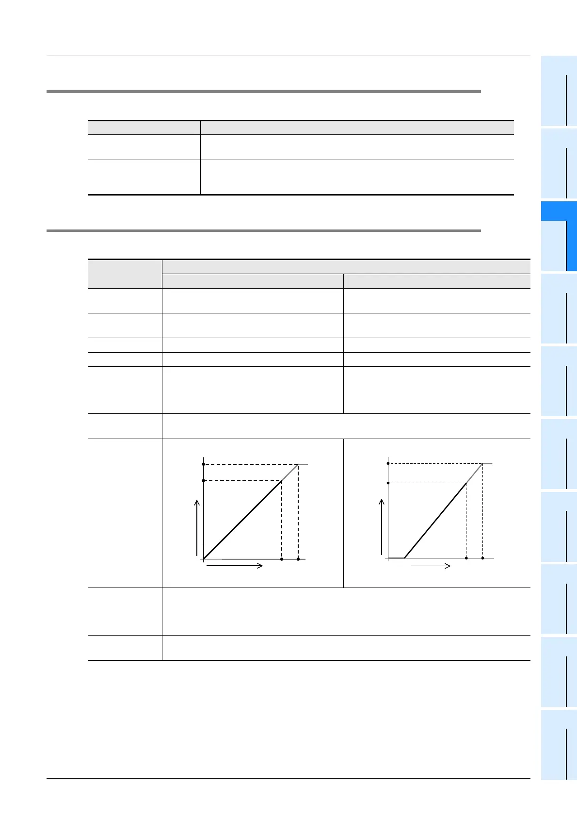
Input
characteristics
Insulation method
• The photo-coupler is used to insulate the analog input area from the PLC.
• The DC/DC converter is used to insulate the driving power supply line from the analog input
area.
• Channels are not insulated from each other.
Number of I/O
occupied points
0 point (This number is not related to the maximum number of input/output points of the PLC.)
0
4000
10V
Approx.
10.2V
4080
Analog input
Digital output
0
1600
20mA
Approx.
20.4mA
1640
Analog input
Digital output
4mA

 Loading...


