D-19
4 Programming
4.7 Model Code
FX
3U
/FX
3UC
Series PLC User's Manual - Analog Control Edition
FX3U-4DA-ADP (4-channel analog Output)
A
Common Items
B
FX
3UC
-4AD
C
FX
3U
-4AD-ADP
D
FX
3U
-4DA-ADP
E
FX
3U
-4AD-PT
-ADP
F
FX
3U
-4AD-TC
-ADP
G
PID Instruction
(FNC 88)
4.7 Model Code
Initial value: K2
Numeric data type: Decimal (K)
1. Description of setting
When 4DA-ADP is connected, model code "2" is stored in the special data register.
The following table shows the special data registers that store the model code:
Use the above special data registers to check whether 4DA-ADP is connected or not.
2. Example of program
4.8 Example of Basic Program
Create the basic example program to output D/A converted analog data.
The following program will set channel 1 to the voltage output mode and channel 2 to current output mode,
and will set digital data in D100 and D101 for D/A conversion.
Using the indicator or the sequence program, input the digital data to be subject to D/A conversion (to be
output as analog data) in D100 and D101.
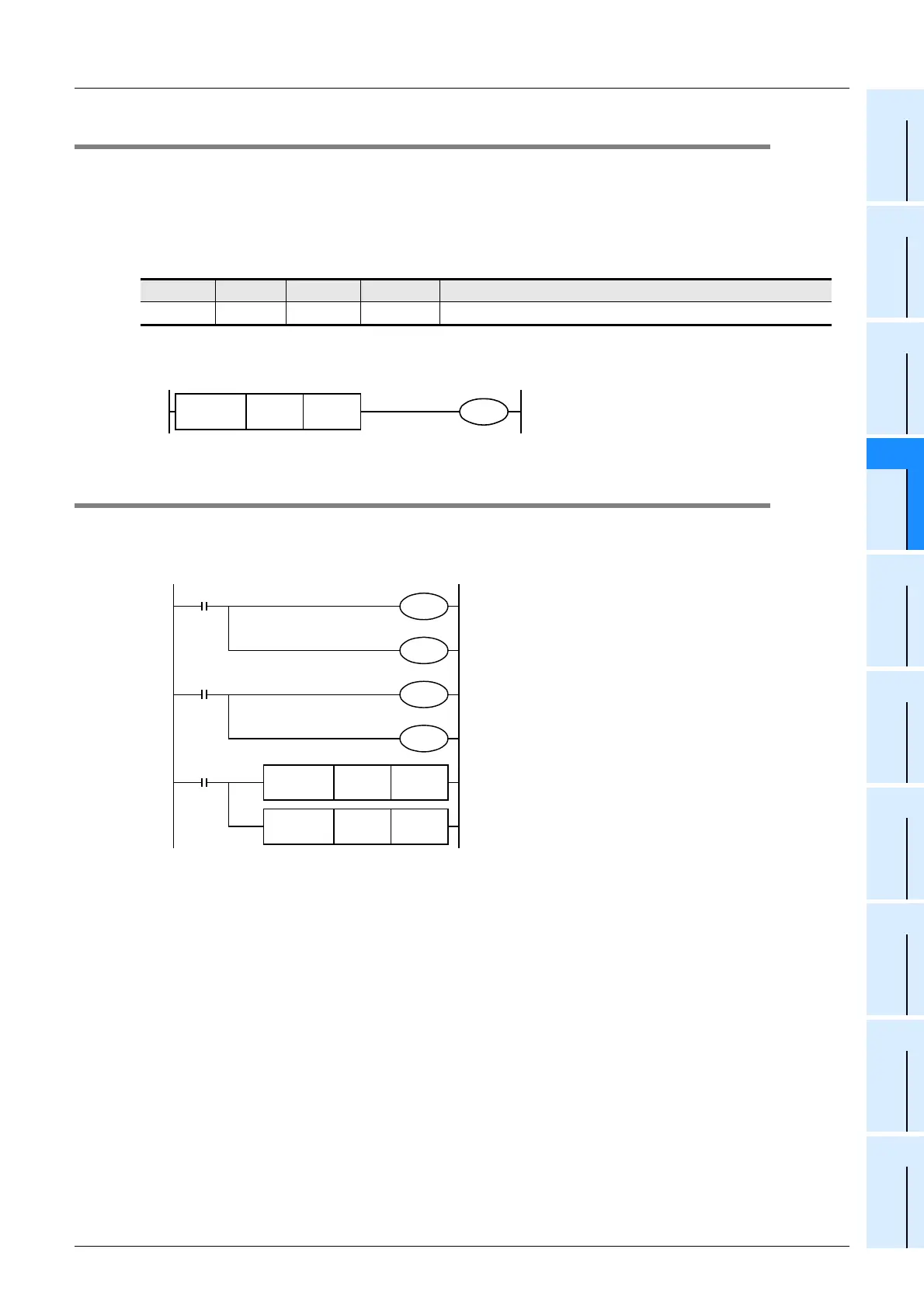
1st 2nd 3rd 4th Description
D8269 D8279 D8289 D8299 Model code
FNC 224
LD =
D8269 K2
Checks the model code
of the 1st analog special
adapter.
Y007
M8001
M8260
M8000
M8261
Sets the output mode of channel 1 to the voltage
output mode (0 V to 10 V).
Sets the output mode of channel 2 to the current
output mode (4 mA to 20 mA).
M8000
FNC 12
MOV
D100 D8260
FNC 12
MOV
D101 D8261
Performs D/A conversion with the digital data stored
in D100 for channel 1.
Performs D/A conversion with the digital data stored
in D101 for channel 2.
M8264
Sets the output holding function for channel 1.
M8265
Cancels the output holding function for channel 2.

 Loading...


