A-9
3 System Configuration Drawings of Analog Products
3.1 FX3U Series PLC
A
Common Items
B
FX
3UC
-4AD
C
FX
3U
-4AD-ADP
D
FX
3U
-4DA-ADP
E
FX
3U
-4AD-PT
-ADP
F
FX
3U
-4AD-TC
-ADP
G
PID Instruction
(FNC 88)
FX
3U
/FX
3UC
Series PLC User's Manual - Analog Control Edition
Common Items
3. System Configuration Drawings of Analog Products
This section shows drawings to describe the configuration of analog units for the FX3U/FX3UC Series PLC.
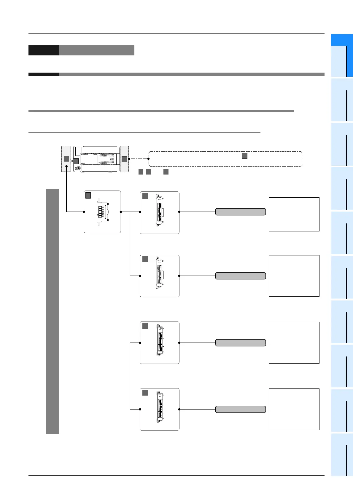
3.1 FX3U Series PLC
3.1.1 Connection of special adapters
*1. FX3U-232-BD, FX3U-485-BD, FX3U-422-BD, FX3U-USB-BD, or FX3U-CNV-BD is needed to connect
the special adapters.
Up to 4 analog special adapters can be connected.
Analog input
•
Flowmeter
•
Pressure sensor
•
Signal converter, etc.
Analog output
•
Inverter, etc.
B C
represent the connecting positions.
For a detailed description of installation, refer to the following manual attached to
your PLC.
J
Refer to the FX
3U
Series User's Manual - Hardware Edition.
CTo connect the special function blocks
refer to the next page.
,
FX
3U
-***-BD*
1
B
European terminal block
RD
RDA
RDB
SDA
SDB
SG
SD
FX
3U
Series
C
A
B
A
FX
3U
-4AD-ADP
FX
3U
-4DA-ADP
FX
3U
-4AD-TC-ADP
FX
3U
-4AD-PT-ADP
European terminal block
European terminal block
European terminal block
Temperature sensor
input
•
Thermocouple
(types K and J)
Temperature sensor
input
•
Platinum resistance
thermometer sensor
(Pt100)
A
A
A
A
and,,

 Loading...


