A-12
3 System Configuration Drawings of Analog Products
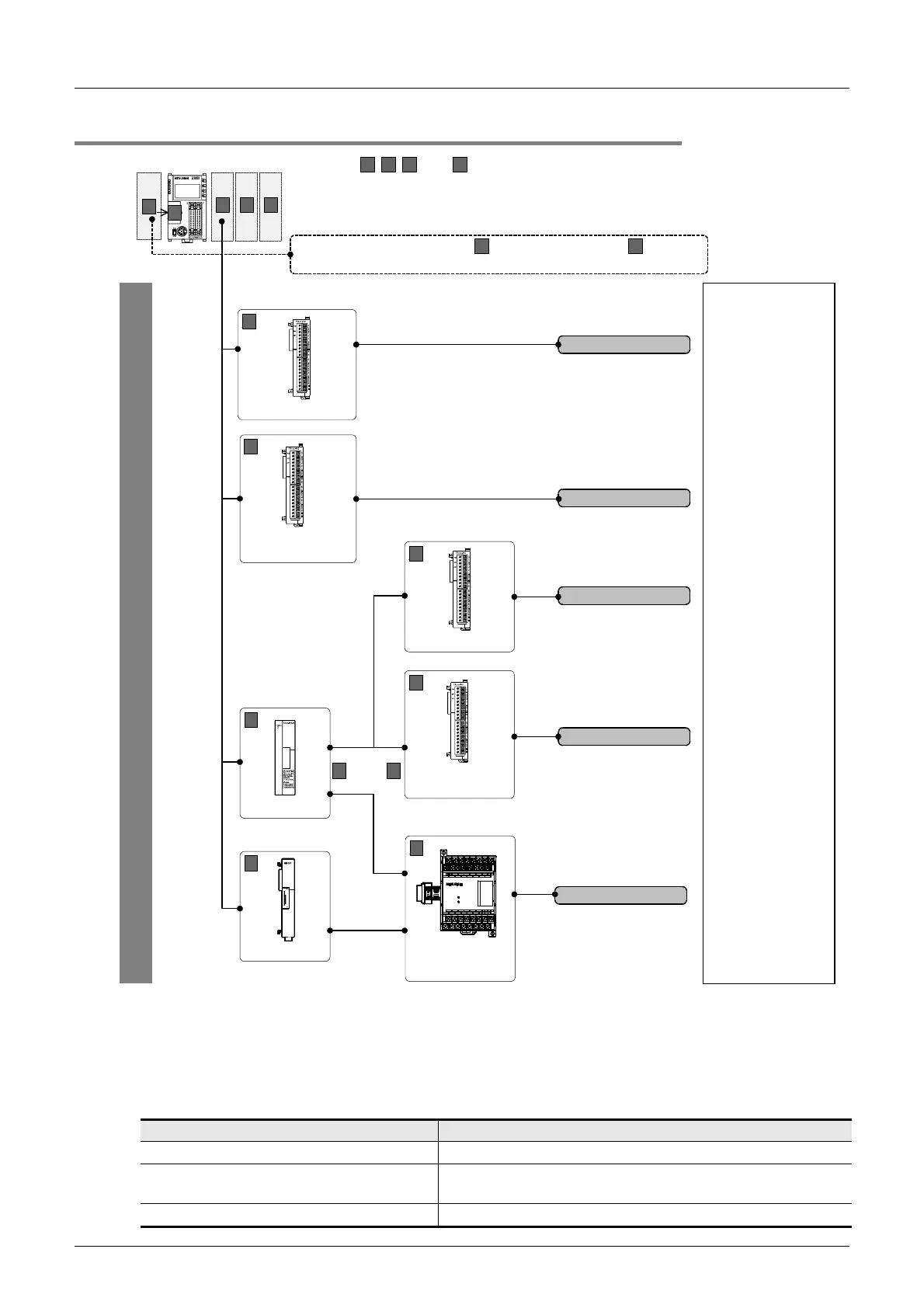
3.2 FX3UC Series PLC
FX
3U
/FX
3UC
Series PLC User's Manual - Analog Control Edition
Common Items
3.2 FX3UC Series PLC
3.2.2 Connection of special function blocks
• For a detailed description of connectability of the special function block and system configuration:
→ Refer to the FX
3UC Series User's Manual - Hardware Edition.
• Use the FX
3UC-1PS-5V (extension power supply unit) if the capacity of the 5V DC power supply unit
incorporated in the FX
3UC Series PLC is deteriorated.
→ Refer to the FX
3UC Series User's Manual - Hardware Edition.
The following analog special function blocks for the FX2NC, FX2N and FX0N can be connected to the FX3UC
Series PLC:
FX Series Type
Analog special function blocks for the FX2NC FX2NC-4AD, FX2NC-4DA
Analog special function blocks for the FX
2N
FX2N-8AD, FX2N-4AD, FX2N-2AD, FX2N-4DA, FX2N-2DA,
FX
2N-5A, FX2N-4AD-PT, FX2N-4AD-TC, FX2N-2LC
Analog special function blocks for the FX
0N FX0N-3A
C1
A
B
D
C2
Up to 7 special function blocks can be connected.
B C
represent the connecting positions.
For a detailed description of installation, refer to the following manual attached to
your PLC.
→
Refer to the FX
3UC
Series User's Manual - Hardware Edition.
A
, and,,
C1
FX
3UC
-4AD
D
FX
3UC
-1PS-5V
Analog input
•
Flowmeter
•
Pressure sensor
•
Signal converter, etc.
Analog output
•
Inverter, etc.
Temperature sensor
input
•
Thermocouple
•
Platinum resistance
thermometer
sensor (Pt100)
European terminal block
C1
Special function
block for FX
2NC
European terminal block
C1
FX
3UC
-4AD
European terminal block
B
refer to the previous page.
A
To connect the special adapters or the expansion boards
,
C1
Special function
block for FX
2NC
European terminal block
C2
Special function
block for
FX
2N
and FX
0N
V8+
COM7
COM6
I6+
I7+
V6+
V5+
COM4
I1+V1+
V7+
V4+I2+V2+
24V
POWER
24-24+
I5+
COM8
COM5
COM1 COM3I3+V3+
I4+
I8+
COM2
FX
2N
-8AD
Terminal block
D
FX
2NC
-CNV-IF
C1 C2
or
FX
3UC
Series
D

 Loading...


