3. SIGNALS AND WIRING
3 - 69
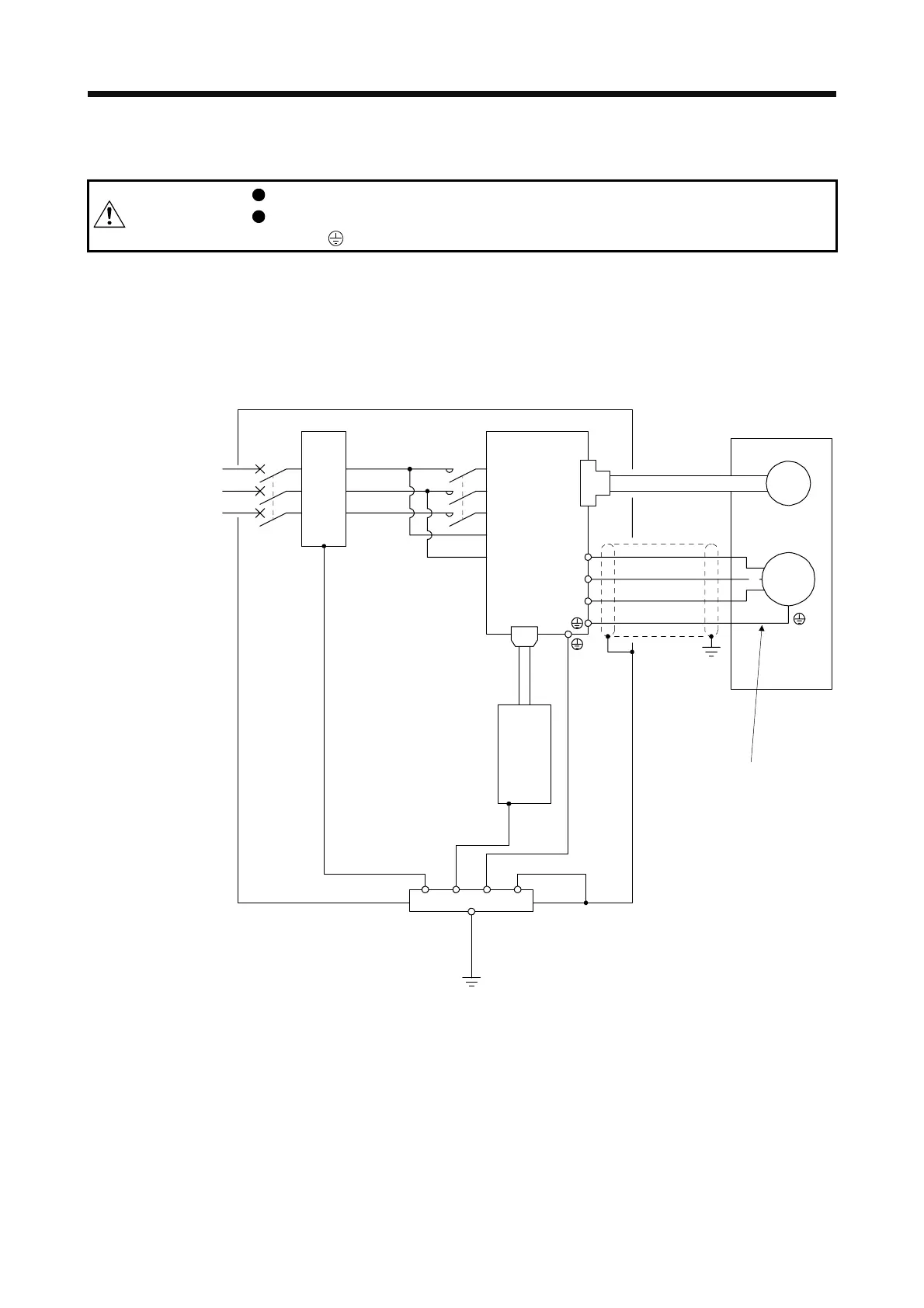
3.11 Grounding
WARNING
Ground the servo amplifier and servo motor securely.
To prevent an electric shock, always connect the protective earth (PE) terminal
(marked
) of the servo amplifier to the protective earth (PE) of the cabinet.
The servo amplifier switches the power transistor on-off to supply power to the servo motor. Depending on
the wiring and ground cable routing, the servo amplifier may be affected by the switching noise (due to di/dt
and dv/dt) of the transistor. To prevent such a fault, refer to the following diagram and always ground.
To conform to the EMC Directive, refer to the EMC Installation Guidelines (IB(NA)67310).
Ensure to connect the
wire to the PE terminal
of the servo amplifier.
Do not connect the wire
directly to the grounding
of the cabinet.
Line filter
(Note)
Power
supply
V
U
Cabinet
Servo motor
M
U
V
W
W
Encoder
CN2
Servo amplifier
L11
L1
L2
L3
L21
CN1
Protective earth (PE)
Outer
box
MC
MCCB
Programmable
Note. For 1-phase 200 V AC to 240 V AC, connect the power supply to L1 and L3. Leave L2 open. For the power
supply specifications, refer to section 1.3.
 Loading...
