14. COMMUNICATION FUNCTION
14 - 1
14. COMMUNICATION FUNCTION
POINT
RS-422 serial communication function is supported by servo amplifier with
software version A3 or later.
The USB communication function (CN5 connector) and the RS-422
communication function (CN3 connector) are mutually exclusive functions. They
cannot be used together.
You can operate servo driving, parameter change, monitor function, etc. using RS-422 serial communication
function with the servo amplifier.
14.1 Structure
14.1.1 Configuration diagram
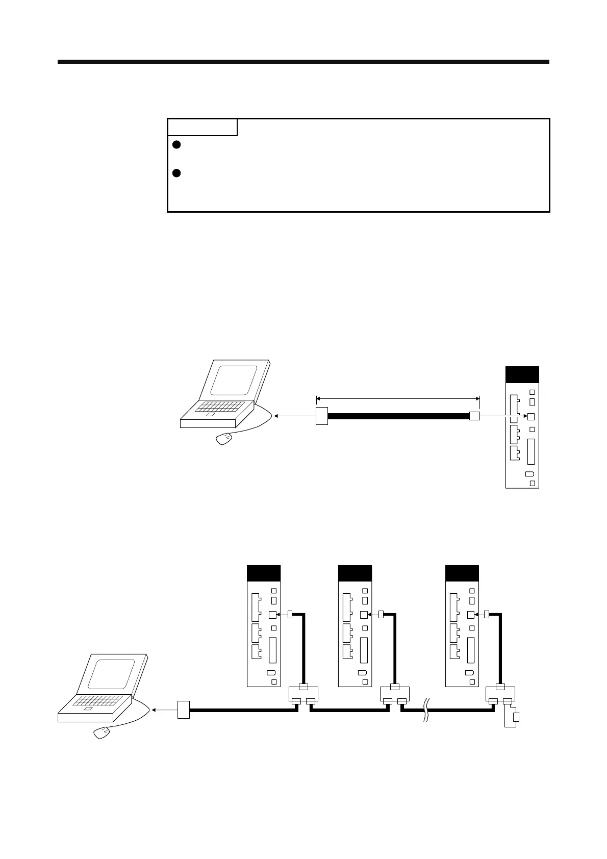
(1) Single axis
Operate the single-axis servo amplifier. It is recommended to use the following cable.
To RS-232C
connector
Servo amplifier
Personal compute
RS-422/232C conversion cable
DSV-CABV (Diatrend)
10 m or less
CN3
(2) Multi-drop connection
(a) Diagrammatic sketch
Up to 32 axes of servo amplifiers from stations 0 to 31 can be operated on the same bus.
To RS-232C
connector
RS-422/232C conversion cable
DSV-CABV (Diatrend)
Personal computer
(Note 1)
(Note 2)
(Note 1)(Note 1)
Servo amplifie
CN3
Servo amplifie
CN3
Servo amplifie
CN3
Note 1. The BMJ-8 (Hachiko Electric) is recommended as the branch connector.
2. The final axis must be terminated between RDP (pin No.3) and RDN (pin No.6) on the receiving side (servo amplifier) with a
150 Ω resistor.
 Loading...
