APPENDIX
App. - 39
App. 7 Analog monitor
POINT
A voltage of analog monitor output may be irregular at power-on.
The servo status can be output to two channels in terms of voltage.
(1) Setting
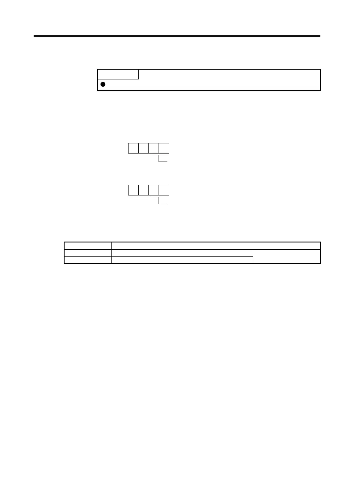
Change the following digits of [Pr. PC14] and [Pr. PC15].
Analog monitor 1 output selection
(the signal provided to the output across MO1 and LG)
00
[Pr. PC14]
Analog monitor 2 output selection
(the signal provided to the output across MO2 and LG)
00
[Pr. PC15]
[Pr. PC39] and [Pr. PC40] can be used to set the offset voltages to the analog output voltages. The
setting range is between -9999 mV and 9999 mV.
Parameter Description Setting range [mV]
PC39 This is used to set the offset voltage of MO1 (Analog monitor 1).
PC40 This is used to set the offset voltage of MO2 (Analog monitor 2).
-9999 to 9999
 Loading...
