17. FULLY CLOSED LOOP SYSTEM
17 - 7
17.2.3 Configuration diagram of encoder cable
Configuration diagram for servo amplifier and load-side encoder is shown below. Cables used vary,
depending on the load-side encoder.
(1) Linear encoder
Refer to Linear Encoder Instruction Manual for encoder cables for linear encoder.
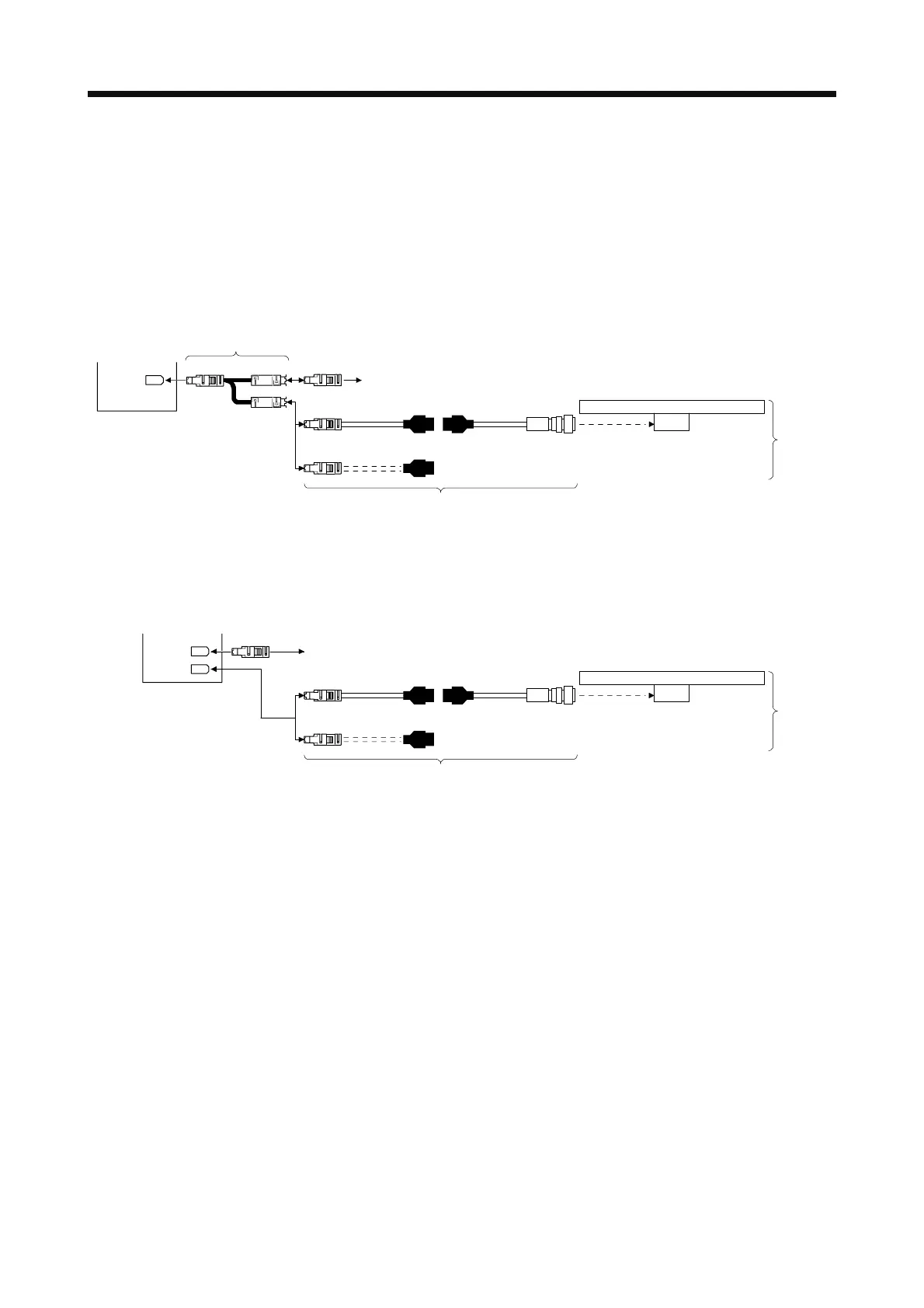
(a) MR-J4-_A_ servo amplifier
Servo amplifier
Linear encoder
CN2
MR-J4FCCBL03M branch cable
(Refer to section 17.2.4)
Encoder of rotary servo motor
Encoder cable
(Refer to the Linear Encoder Instruction Manual.)
CN2 MOTOR
SCALE
Load-side
encoder
(b) MR-J4-_A_-RJ servo amplifier
You can connect the linear encoder without using a branch cable shown in (a) for MR-J4-_A_-RJ
servo amplifier. You can also use a four-wire type linear encoder.
Servo amplifier
Linear encoder
CN2
Encoder of rotary servo motor
CN2L
Encoder cable
(Refer to the Linear Encoder Instruction Manual.)
Load-side
encoder
 Loading...
