15. USING A LINEAR SERVO MOTOR
15 - 2
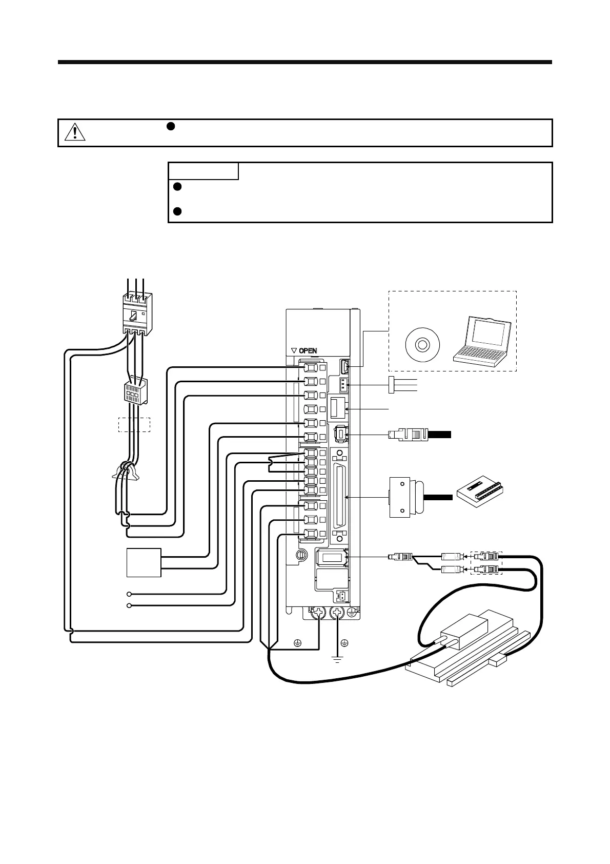
15.1.2 Configuration including peripheral equipment
CAUTION
Connecting a linear servo motor of the wrong axis to the U, V, W, or CN2 may
cause a malfunction.
POINT
Equipment other than the servo amplifier and linear servo motor are optional or
recommended products.
When using the linear servo motor, set [Pr. PA01] to "_ _ 4 _".
(1) MR-J4-_A_
The following configuration diagram shows an example for using a linear servo motor with MR-J4-10A.
Line noise
filter
(FR-BSF01)
CN5
Regenerative
option
P+
C
L11
L21
P3
P4
Personal
computer
MR Configurator2
CN3
CN6
CN8
CN1
CN2
W
V
U
Magnetic
contactor
L1
L2
L3
(Note 3)
(Note1)
(MC)
Power factor
improving
DC reactor
(FR-HEL)
Molded-case
circuit breaker
To safety relay or
MR-J3-D05 safety logic unit
Analog monitor
Junction terminal block
Power supply
(Note 2)
Personal computer and others
D
(Note 5)
(Note 4)
Linear encoder
Linear servo motor
Encoder
cable
SCALE
THM
RS T
(MCCB)
(Note 6)
Thermistor
Note 1. The power factor improving AC reactor can also be used. In this case, the power factor improving DC reactor cannot be used.
When not using the power factor improving DC reactor, short P3 and P4.
2. A 1-phase 200 V AC to 240 V AC power supply may be used with the servo amplifier of MR-J4-70A or less. For 1-phase 200 V
AC to 240 V AC, connect the power supply to L1 and L3. Leave L2 open. For the power supply specifications, refer to section
1.3.
3. Depending on the main circuit voltage and operation pattern, bus voltage decreases, and that may cause the forced stop
deceleration to shift to the dynamic brake deceleration. When dynamic brake deceleration is not required, slow the time to turn
off the magnetic contactor.
4. For the branch cable, use the MR-J4THCBL03M (optional).
5. Always connect between P+ and D terminals. When using the regenerative option, refer to section 11.2.
6. Connect the thermistor to THM of branch cable and connect the encoder cable to SCALE correctly. Incorrect setting will trigger
[AL. 16].
 Loading...
