68 / 195
Service Manual Mitsubishi SL-Series diesel engines
Version 08/2004
ENGLISH
TIMING GEARS AND FLYWHEEL INSPECTION
68 / 195
2) Installation
Install a new bushing in position with its oil
holes in alignment with those of the oil gallery.
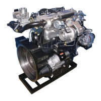
3. Lobe lift
Measure the lobe height and base circle as shown in
the illustration. Subtract the base circle from the lobe
height to find the lobe life. If the lobe lift exceeds the
limit, replace the camshaft
.Unit: mm (in.)
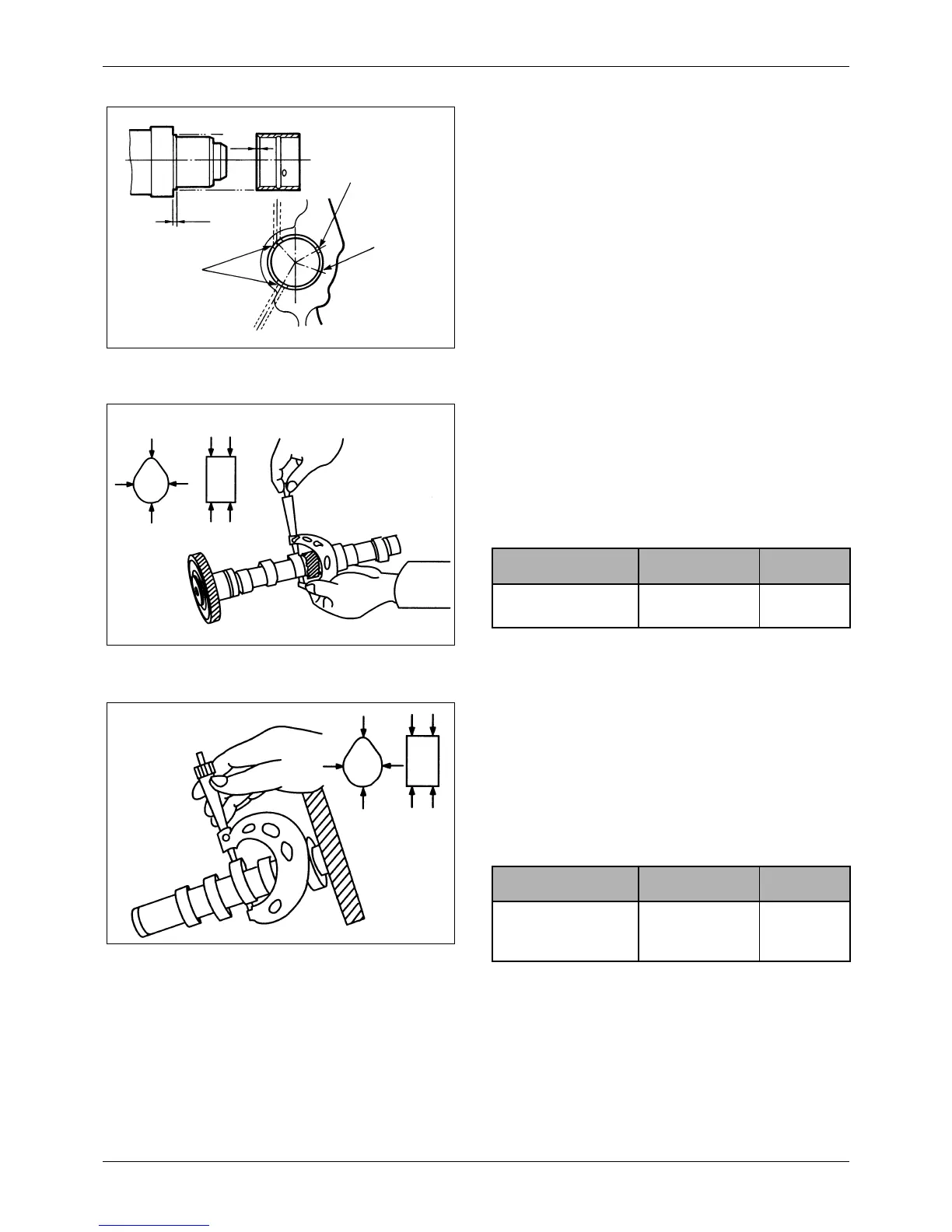
18.2 Fuel injection pump camshaft
Measure the lobe height and base circle as shown in
the illustration. Subtract the base circle from the lobe
height to find the lobe life. If the lobe lift exceeds the
limit, replace the camshaft.
.Unit: mm (in.)
Figure 84 Installing camshaft bushing
1 mm (0.04 in.)
Notch in
bushing
1 mm (0.04 in.)
Ends of
bushing
Oil holes
Figure 85 Measuring lobe height of camshaft
Item Standard Limit
Lobe height of
camshaft
35.72
(1.404 3)
34.72
(1.366 9)
Figure 86 Measuring lobe height of fuel injection
pump camshaft
Item Standard Limit
Lobe height of fuel
injection pump
camshaft
44
(1.73)
43
(1.69)

 Loading...