120 / 195
Service Manual Mitsubishi SL-Series diesel engines
Version 08/2004
ENGLISH
STARTER ELECTRICAL SYSTEM
120 / 195
29.4 Inspection and Testing after
Assembly
After assembling the starter, perform the following
inspections and tests:
29.4.1 Inspection and Adjustment of
Pinion Gap
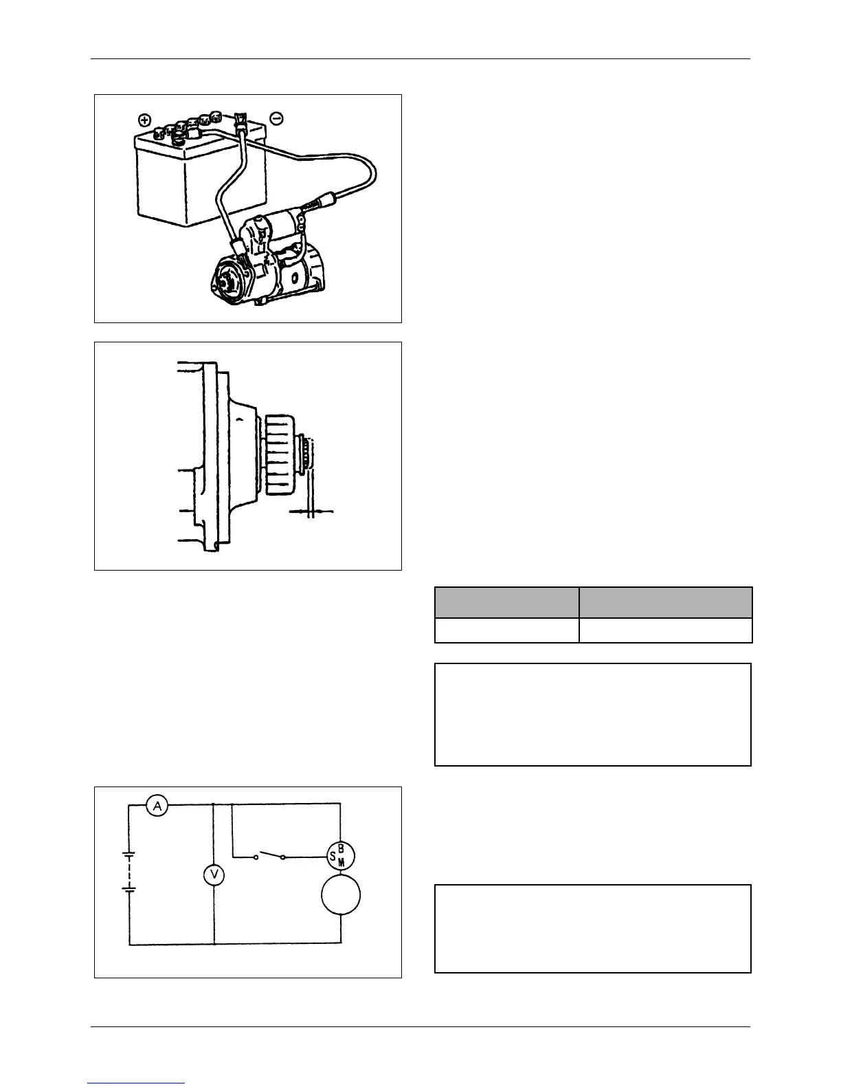
1. Connect the assembled starter to the battery as
shown in the drawing. The pinion will come out and
rotate slowly. Then, remove the M-terminal
connector to stop the motor.
2. Lightly push the pinion shaft toward the armature
and measure the amount of axial movement,
which corresponds to the pinion gap.
3. If the pinion gap is not within the 0.5 – 2.0 mm
(0.02 – 0.08 in.) range, adjust it by increasing or
decreasing the number of seals in the solenoid
switch. (Increasing the number of seals reduce the
pinion gap). It may be necessary to replace the
lever to obtain the correct pinion gap.
Unit: mm (in.)
29.4.2 No-Load Test
When the pinion gap has been correctly adjusted,
connect an ammeter and a voltmeter between the
starter motor and battery as shown in the drawing, then
check the starter’s no-load characteristics.
Battery (12V)
S-terminal
M-terminal
Pinion gap
Standard value
Pinion gap 0.5 – 2.0 (0.02 – 0.08)
NOTE
To prevent the solenoid switch coil from overheating,
do not energize the solenoid switch for longer than 10
seconds.
Switch
Battery
(12V)
Voltmeter
Starter
Motor
Ammeter
Switch
CAUTION
Use the thickest wires possible, and tighten each
terminal firmly.

 Loading...