EasyManuals Logo
Home>Motorola>Portable Radio>P100 Series

Motorola P100 Series Detailed Service Manual

Motorola P100 Series
336 pages
To Next Page IconTo Next Page
To Previous Page IconTo Previous Page
Page #151 background imageLoading...
Page #151 background image
Chapter 8 136 – 174 MHz VHF Theory of Operation
8.1 Introduction
This chapter provides a detailed theory of operation for the radio components. Schematic diagrams
for the circuits described in the following paragraphs are located in Chapter 10 of this manual.
8.2 VHF Receiver
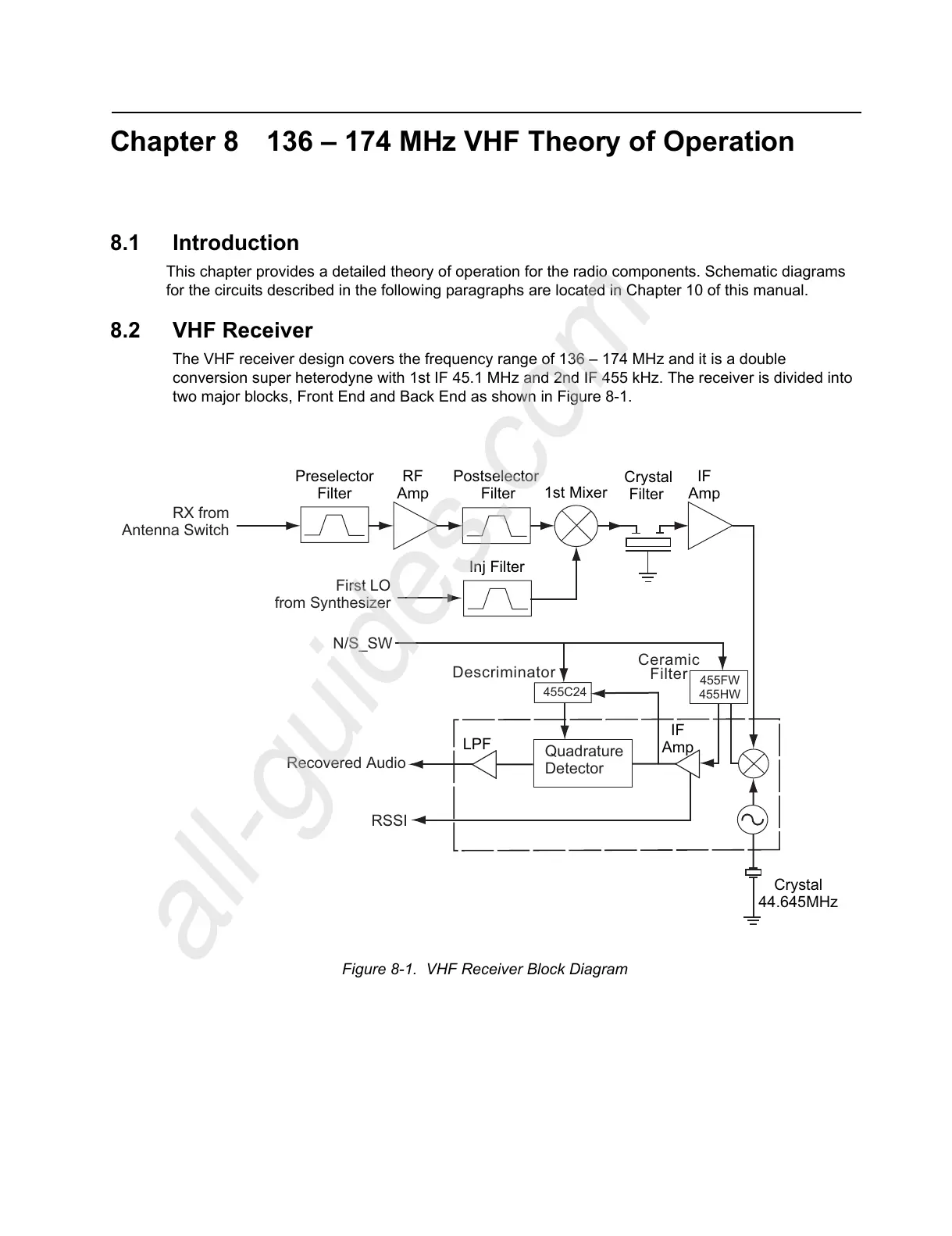
The VHF receiver design covers the frequency range of 136 – 174 MHz and it is a double
conversion super heterodyne with 1st IF 45.1 MHz and 2nd IF 455 kHz. The receiver is divided into
two major blocks, Front End and Back End as shown in Figure 8-1.
Figure 8-1. VHF Receiver Block Diagram
Crystal
Filter
Crystal
44.645MHz
1st Mixer
RF
Amp
Preselector
Filter
Postselector
Filter
RX from
A
ntenna Switch
Inj Filter
First LO
from Synthesizer
IF
Amp
IF
Amp
LPF
Ceramic
Filter
Descriminator
455FW
455HW
Quadrature
Detector
RSSI
N/S_SW
Recovered Audio
455C24
All manuals and user guides at all-guides.com
all-guides.com

Table of Contents

Other manuals for Motorola P100 Series

Questions and Answers:

Question and Answer IconNeed help?

Do you have a question about the Motorola P100 Series and is the answer not in the manual?

Motorola P100 Series Specifications

General IconGeneral
BrandMotorola
ModelP100 Series
CategoryPortable Radio
LanguageEnglish

Related product manuals