EasyManuals Logo
Home>Motorola>Portable Radio>P100 Series

Motorola P100 Series Detailed Service Manual

Motorola P100 Series
336 pages
To Next Page IconTo Next Page
To Previous Page IconTo Previous Page
Page #156 background imageLoading...
Page #156 background image
8-6 136 – 174 MHz VHF Theory of Operation: Keypad
8.5 Keypad
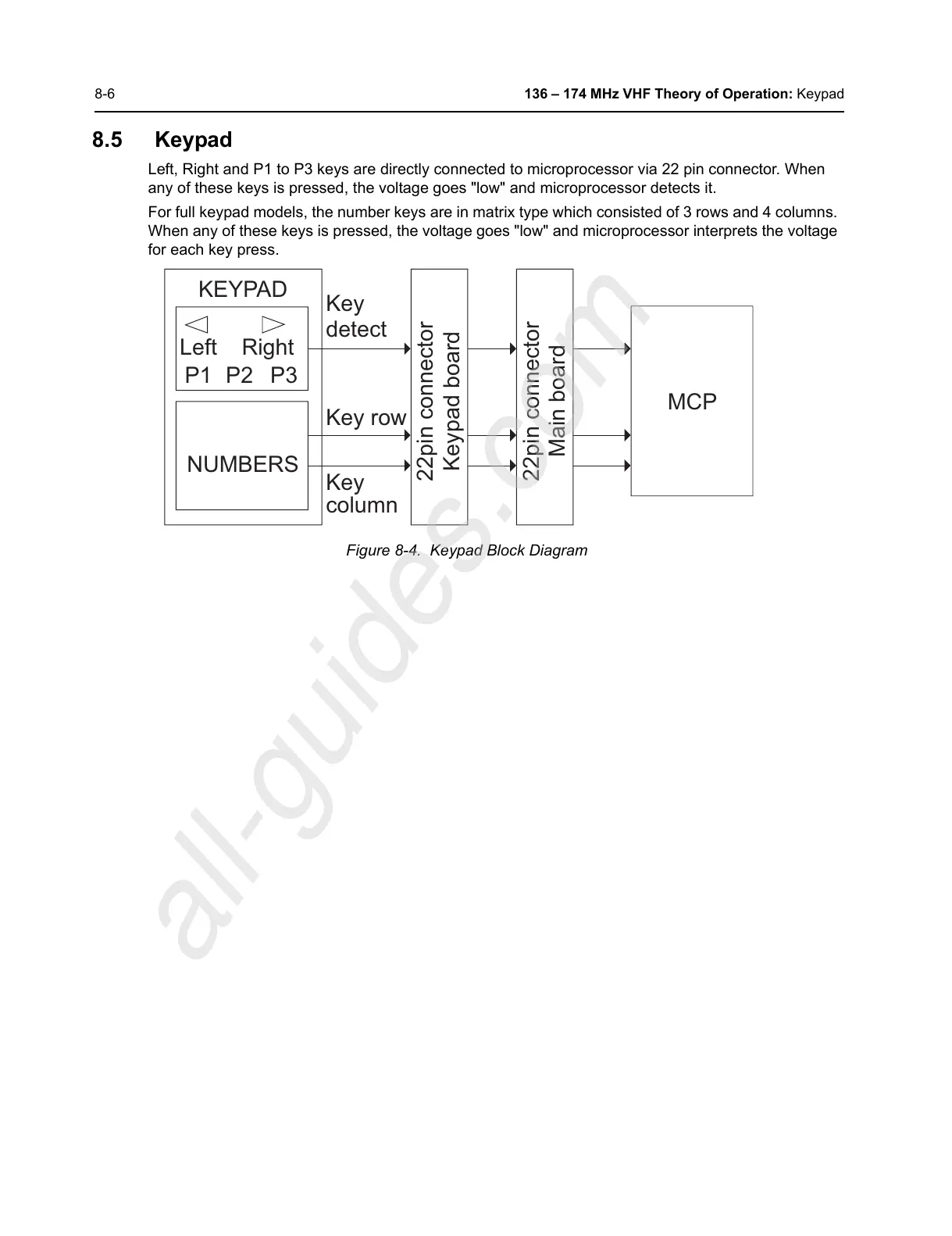
Left, Right and P1 to P3 keys are directly connected to microprocessor via 22 pin connector. When
any of these keys is pressed, the voltage goes "low" and microprocessor detects it.
For full keypad models, the number keys are in matrix type which consisted of 3 rows and 4 columns.
When any of these keys is pressed, the voltage goes "low" and microprocessor interprets the voltage
for each key press.
Figure 8-4. Keypad Block Diagram
KEYPAD
Left
NUMBERS
Right
P1 P2 P3
Key
Key row
Key
column
22pin connector
Keypad board
22pin connector
Main board
MCP
detect
All manuals and user guides at all-guides.com
all-guides.com

Table of Contents

Other manuals for Motorola P100 Series

Questions and Answers:

Question and Answer IconNeed help?

Do you have a question about the Motorola P100 Series and is the answer not in the manual?

Motorola P100 Series Specifications

General IconGeneral
BrandMotorola
ModelP100 Series
CategoryPortable Radio
LanguageEnglish

Related product manuals