UHF1 Troubleshooting Tables: Troubleshooting Table for Transmitter (UHF1) 12-3
12.3 Troubleshooting Table for Transmitter (UHF1)
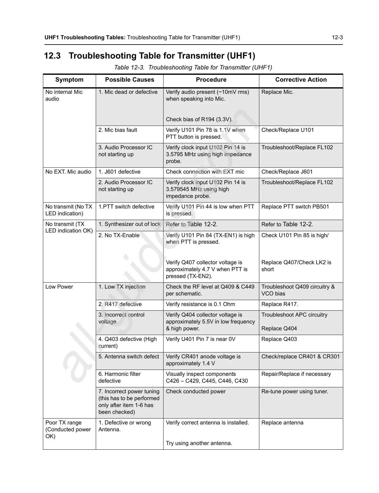
Table 12-3. Troubleshooting Table for Transmitter (UHF1)
Symptom Possible Causes Procedure Corrective Action
No internal Mic
audio
1. Mic dead or defective Verify audio present (~10mV rms)
when speaking into Mic.
Check bias of R194 (3.3V).
Replace Mic.
2. Mic bias fault Verify U101 Pin 78 is 1.1V when
PTT button is pressed.
Check/Replace U101
3. Audio Processor IC
not starting up
Verify clock input U102 Pin 14 is
3.5795 MHz using high impedance
probe.
Troubleshoot/Replace FL102
No EXT. Mic audio 1. J601 defective Check connection with EXT mic Check/Replace J601
2. Audio Processor IC
not starting up
Verify clock input U102 Pin 14 is
3.579545 MHz using high
impedance probe.
Troubleshoot/Replace FL102
No transmit (No TX
LED indication)
1.PTT switch defective Verify U101 Pin 44 is low when PTT
is pressed.
Replace PTT switch PB501
No transmit (TX
LED indication OK)
1. Synthesizer out of lock
Refer to Table 12-2. Refer to Table 12-2.
2. No TX-Enable Verify U101 Pin 84 (TX-EN1) is high
when PTT is pressed.
Verify Q407 collector voltage is
approximately 4.7 V when PTT is
pressed (TX-EN2).
Check U101 Pin 85 is high/
Replace Q407/Check LK2 is
short
Low Power
1. Low TX injection Check the RF level at Q409 & C449
per schematic.
Troubleshoot Q409 circuitry &
VCO bias
2. R417 defective Verify resistance is 0.1 Ohm Replace R417.
3. Incorrect control
voltage
Verify Q404 collector voltage is
approximately 5.5V in low frequency
& high power.
Troubleshoot APC circuitry
Replace Q404
4. Q403 defective (High
current)
Verify U401 Pin 7 is near 0V Replace Q403
5. Antenna switch defect Verify CR401 anode voltage is
approximately 1.4 V
Check/replace CR401 & CR301
6. Harmonic filter
defective
Visually inspect components
C426 – C429, C445, C446, C430
Repair/Replace if necessary
7. Incorrect power tuning
(this has to be performed
only after item 1-6 has
been checked)
Check conducted power Re-tune power using tuner.
Poor TX range
(Conducted power
OK)
1. Defective or wrong
Antenna.
Verify correct antenna is installed.
Try using another antenna.
Replace antenna
 Loading...