Chapter 3 DC Power Distribution
3.1 DC Regulation and Distribution
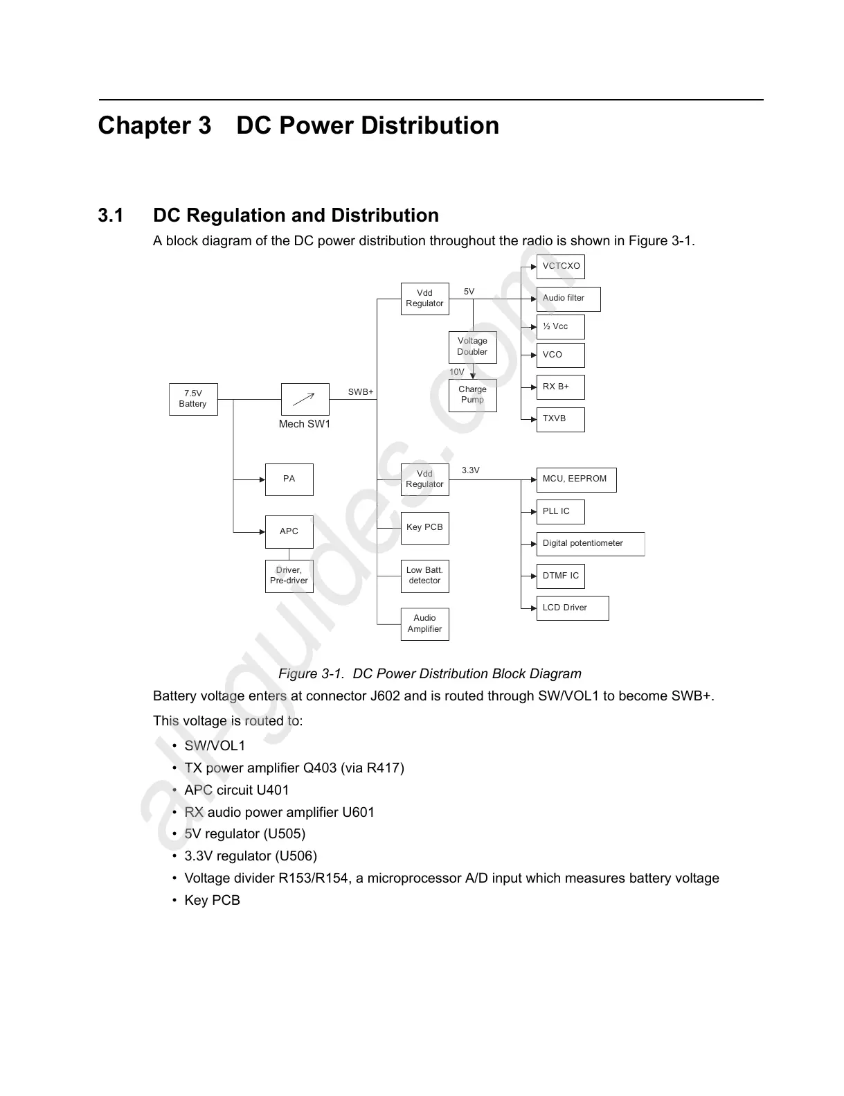
A block diagram of the DC power distribution throughout the radio is shown in Figure 3-1.
Figure 3-1. DC Power Distribution Block Diagram
Battery voltage enters at connector J602 and is routed through SW/VOL1 to become SWB+.
This voltage is routed to:
•SW/VOL1
• TX power amplifier Q403 (via R417)
• APC circuit U401
• RX audio power amplifier U601
• 5V regulator (U505)
• 3.3V regulator (U506)
• Voltage divider R153/R154, a microprocessor A/D input which measures battery voltage
•Key PCB
Audio filter
LCD Driver
DTMF IC
Digital potentiometer
PLL IC
MCU, EEPROM
TXVB
RX B+
VCO
½ Vcc
VCTCXO
Voltage
Doubler
Vdd
Regulator
Charge
Pump
5V
10V
Low Batt.
detector
Key PC B
Vdd
Regulator
Audio
Amplifier
3.3V
7.5V
Battery
PA
APC
Driver,
Pre-driver
Mech SW1
SWB+
 Loading...