Chapter 4 Controller Theory of Operation
4.1 RX Audio Circuit
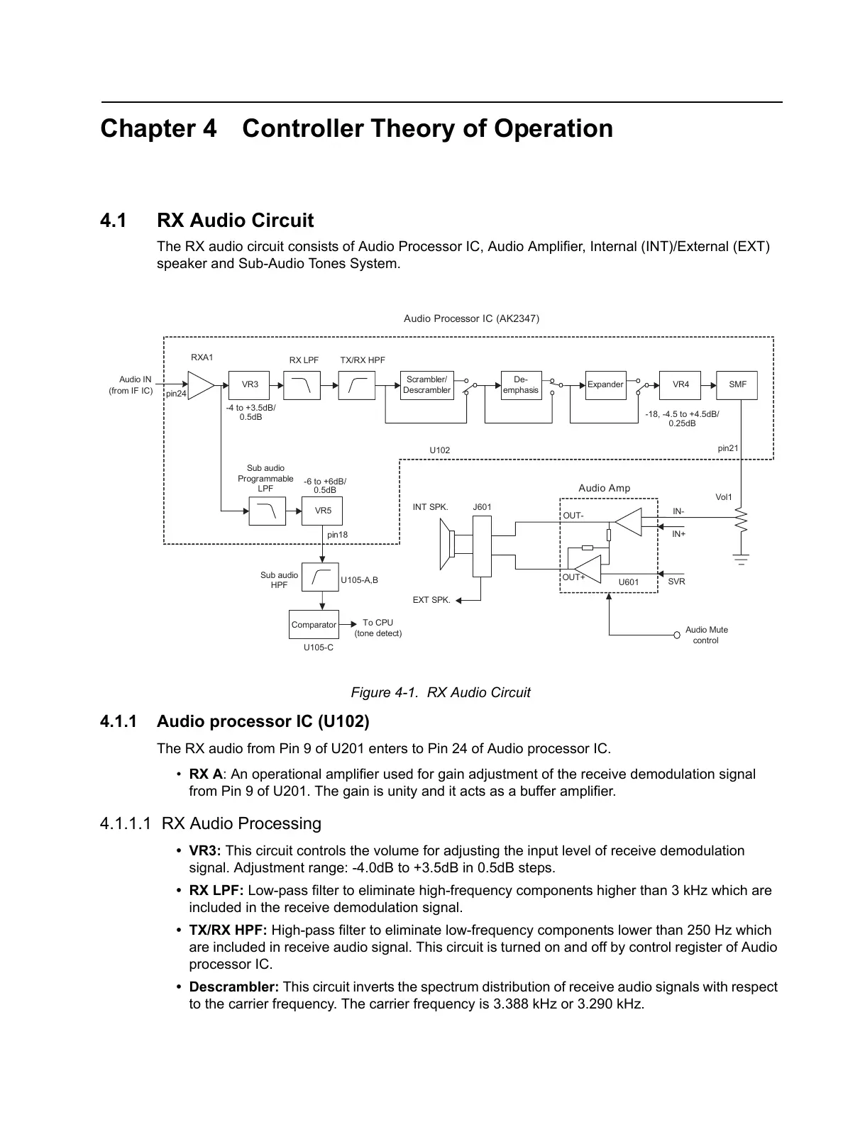
The RX audio circuit consists of Audio Processor IC, Audio Amplifier, Internal (INT)/External (EXT)
speaker and Sub-Audio Tones System.
Figure 4-1. RX Audio Circuit
4.1.1 Audio processor IC (U102)
The RX audio from Pin 9 of U201 enters to Pin 24 of Audio processor IC.
• RX A: An operational amplifier used for gain adjustment of the receive demodulation signal
from Pin 9 of U201. The gain is unity and it acts as a buffer amplifier.
4.1.1.1 RX Audio Processing
•VR3: This circuit controls the volume for adjusting the input level of receive demodulation
signal. Adjustment range: -4.0dB to +3.5dB in 0.5dB steps.
• RX LPF: Low-pass filter to eliminate high-frequency components higher than 3 kHz which are
included in the receive demodulation signal.
• TX/RX HPF: High-pass filter to eliminate low-frequency components lower than 250 Hz which
are included in receive audio signal. This circuit is turned on and off by control register of Audio
processor IC.
• Descrambler: This circuit inverts the spectrum distribution of receive audio signals with respect
to the carrier frequency. The carrier frequency is 3.388 kHz or 3.290 kHz.
VR3
Scrambler/
Descrambler
De-
emphas is
Expander VR4 SMF
SVR
IN-
IN+
OUT-
OUT+
Audio Mute
control
RX LPF TX/RX HPF
RXA1
-4 to +3.5dB/
-18, -4.5 to +4.5dB/
0.25dB
Audio Processor IC (AK2347)
Audio IN
(from IF IC)
VR5
Sub audio
Programmable
LPF
To CPU
(tone detect)
pin24
pin18
pin21
Audio Amp.
U102
U601
Vol1
-6 to +6dB/
0.5dB
INT SPK.
EXT SPK.
J601
Sub audio
HPF
U105-A,B
Comparator
U105-C
0.5dB
 Loading...