403 – 447 MHz UHF1 Theory Of Operation: UHF1 Transmitter 11-3
11.3 UHF1 Transmitter
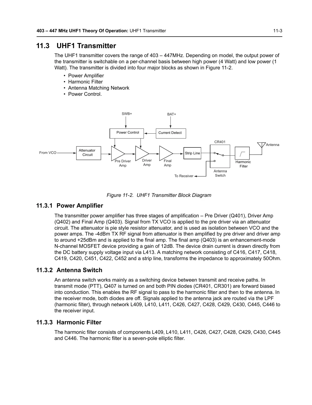
The UHF1 transmitter covers the range of 403 – 447MHz. Depending on model, the output power of
the transmitter is switchable on a per-channel basis between high power (4 Watt) and low power (1
Watt). The transmitter is divided into four major blocks as shown in Figure 11-2.
• Power Amplifier
• Harmonic Filter
• Antenna Matching Network
• Power Control.
Figure 11-2. UHF1 Transmitter Block Diagram
11.3.1 Power Amplifier
The transmitter power amplifier has three stages of amplification – Pre Driver (Q401), Driver Amp
(Q402) and Final Amp (Q403). Signal from TX VCO is applied to the pre driver via an attenuator
circuit. The attenuator is pie style resistor attenuator, and is used as isolation between VCO and the
power amps. The -4dBm TX RF signal from attenuator is then amplified by pre driver and driver amp
to around +25dBm and is applied to the final amp. The final amp (Q403) is an enhancement-mode
N-channel MOSFET device providing a gain of 12dB. The device drain current is drawn directly from
the DC battery supply voltage input via L413. A matching network consisting of C416, C417, C418,
C419, C420, C451, C422, C452 and a strip line, transforms the impedance to approximately 50Ohm.
11.3.2 Antenna Switch
An antenna switch works mainly as a switching device between transmit and receive paths. In
transmit mode (PTT), Q407 is turned on and both PIN diodes (CR401, CR301) are forward biased
into conduction. This enables the RF signal to pass to the harmonic filter and then to the antenna. In
the receiver mode, both diodes are off. Signals applied to the antenna jack are routed via the LPF
(harmonic filter), through network L409, L410, L411, C426, C427, C428, C429, C430, C445, C446 to
the receiver input.
11.3.3 Harmonic Filter
The harmonic filter consists of components L409, L410, L411, C426, C427, C428, C429, C430, C445
and C446. The harmonic filter is a seven-pole elliptic filter.
Attenuator
Circuit
Pre Driver
Amp
From VCO
Driver
Amp
Final
Amp
Power Control
Strip Line
Current Detect
SWB+
BAT+
Antenna
Switch
To Receiver
CR401
Harmonic
Filter
Antenna
 Loading...