Apex Classic Setup and Programming Guide v2.2 Page 58
CO2_3_7 is OFF Auto
Ozone_3_8 is ON Manual
Power Failed: Mar 01 2010 18:50:42
Power Restored: Mar 01 2010 18:51:11
Power OK: EB8_3 (28 Minutes - 01.6 Amps)
SWITCH INPUTS
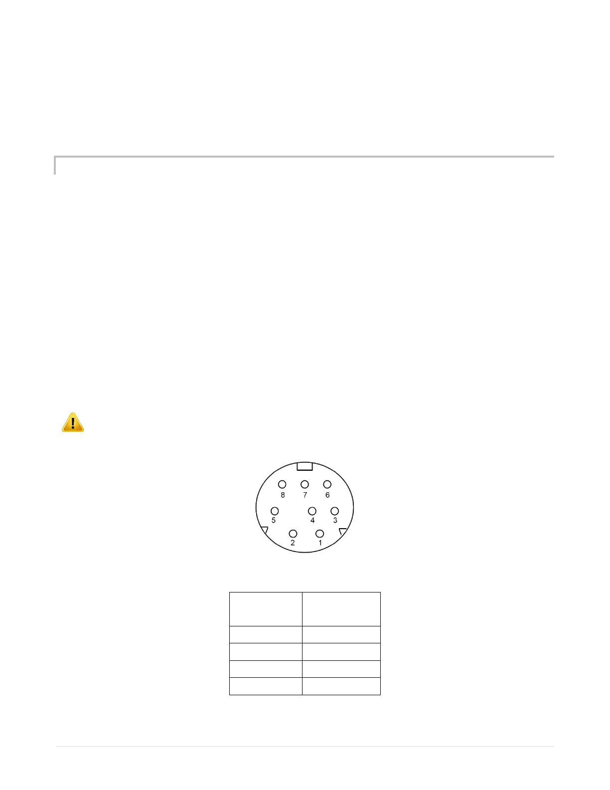
The AquaController Apex has a Mini DIN8 connector for switch inputs labeled I/O.
These inputs can be used for switches, float switches, water sensors, flow
sensors, etc.
Switch inputs on the Base Module are identified as Switch1, Switch3, etc.
Switch inputs on a PX-1000 are identified as SwitchA1, SwitchB4, etc. The letter
is the PX-1000 address assigned to the PX-1000.
Switch inputs connected to probe modules are identified as Switchx3_2,
Switchx5_3, etc. The first number in the switch name corresponds to the
AquaBus address assigned to the probe module. The second number corresponds
to the switch input number (1 - 6).
WARNING: Do not apply voltage to the switch inputs or damage to the
AquaController Apex may occur.
Figure 6 - Switch Input Connector
Number
 Loading...