Front panel model M4350-12X12F
Figure 3. Front panel model M4350-12X12F
From left to right, the front panel of model M4350-12X12F provides the following
common components, which are clearly named or numbered on the front panel:
•
POWER, FAN, STACK MASTER, and STACK ID: System LEDs (see LEDs model
M4350-12X12F on page 18)
•
RESET: Recessed dual-function Reset button (see Dual-function Reset button on
page 38)
•
USB C: One USB Type-C console port (see USB Type-C console port on page 39)
•
12 multispeed Ethernet ports, numbered 1 through 12: Twelve
10G/5G/2.5G/1G/100M autosensing RJ-45 ports, each with a left LED and a right
LED (see LEDs model M4350-12X12F on page 18)
•
12 SFP+ ports, numbered 13 through 24: Twelve 10G/1G SFP+ fiber uplink ports,
each with a combined speed and activity LED (see LEDs model M4350-12X12F on
page 18)
For information about optional devices for the fiber uplink ports, see Fiber transceiver
modules and cables for SFP+ and SFP28 ports on page 37.
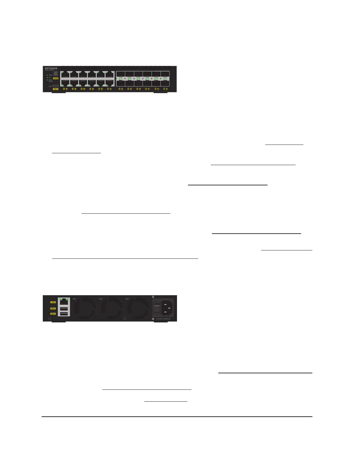
Back panel model M4350-12X12F
Figure 4. Back panel model M4350-12X12F
From left to right, the back panel of model M4350-12X12F provides the following
common components, which are clearly named or numbered on the back panel:
•
OOB: One out-of-band (OOB) 1G Ethernet port (see Out-of-band 1G Ethernet port
on page 39) with a left LED that indicates the speed and a right LED that indicates
the activity (see LEDs model M4350-12X12F on page 18)
•
USB: Two USB 3.0 ports (see USB 3.0 ports on page 39)
•
Fans: Three fans (FAN 1, FAN 2, and FAN 3)
Hardware Installation Guide17Hardware Overview
Fully Managed Switches M4350 Series
 Loading...