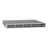
From left to right, the back panel of model M4350-44M4X4V provides the following
common components, which are clearly named or numbered on the back panel:
•
On/Off power switch: One On/Off power switch that lets you turn on or turn off
power to the switch
•
OOB: One out-of-band (OOB) 1G Ethernet port (see Out-of-band 1G Ethernet port
on page 39) with a left LED that indicates the speed and a right LED that indicates
the activity (see LEDs model M4350-24F4V on page 31)
•
USB: Two USB 3.0 ports (see USB 3.0 ports on page 39)
•
Fans: Four fans placed together in one group (FAN 1+ FAN 2 + FAN 3 + FAN 4)
•
AC power receptacle. AC receptacle for the internal PSU. The PSU can accept
100–240V ~ 50–60 Hz, 10A.
•
PSU bays: Two PSU bays (PSU 1 and PSU 2) that are closed with PSU covers. For
information about ordering optional APSs that you can install in the PSU bays, contact
NETGEAR.
LEDs model M4350-44M4X4V
This section describes the LED designations of model M4350-44M4X4V. The LEDs are
clearly named or numbered on the front and back panels.
Table 7. LEDs of model M4350-44M4X4V
DescriptionLED
System LEDs, Front Panel
Solid green: The switch is powered on and operating normally.
Solid yellow: The switch is starting.
Off: Power is not supplied to the switch.
POWER LED
Solid green: The fans are functioning normally.
Solid yellow: One or more fans are malfunctioning.
FAN LED
Off: Sufficient (more than 7W of) PoE power is available.
Solid yellow: Less than 7W of PoE power is available.
Blinking yellow: At least once during the previous two minutes, less than 7W
of PoE power was available.
PoE MAX LED
Solid green: The switch is functioning as the stack management switch.
Off: The switch is functioning as a stack member switch or is not a member of
a stack.
STACK MASTER LED
Hardware Installation Guide34Hardware Overview
Fully Managed Switches M4350 Series
 Loading...