English – 11
10. Manually open the door to the desired posi-
tion.
Shift the rear mechanical stop Q, then place
it alongside the motor carriage and lock it by
vigorously tightening screw P
1
3
Q
2
P
Q
P
11. Try to move the door manually. Check that the motor carriage slides smoothly without any friction on the guide and that manual ma-
noeuvre does not require excessive force.
To install the specied accessories, refer to the respective instruction manuals.
4
ELECTRICAL CONNECTIONS
WARNING! – All electrical connections must be made with the system disconnected from the power supply. Incorrect connec-
tions can cause damage to the equipment and injury to people.
WARNING! – The cables used must be suited to the type of installation; for example a type-H03VV-F cable is recommended for
indoor environments, and a type-H07RN-F cable for outdoor environments.
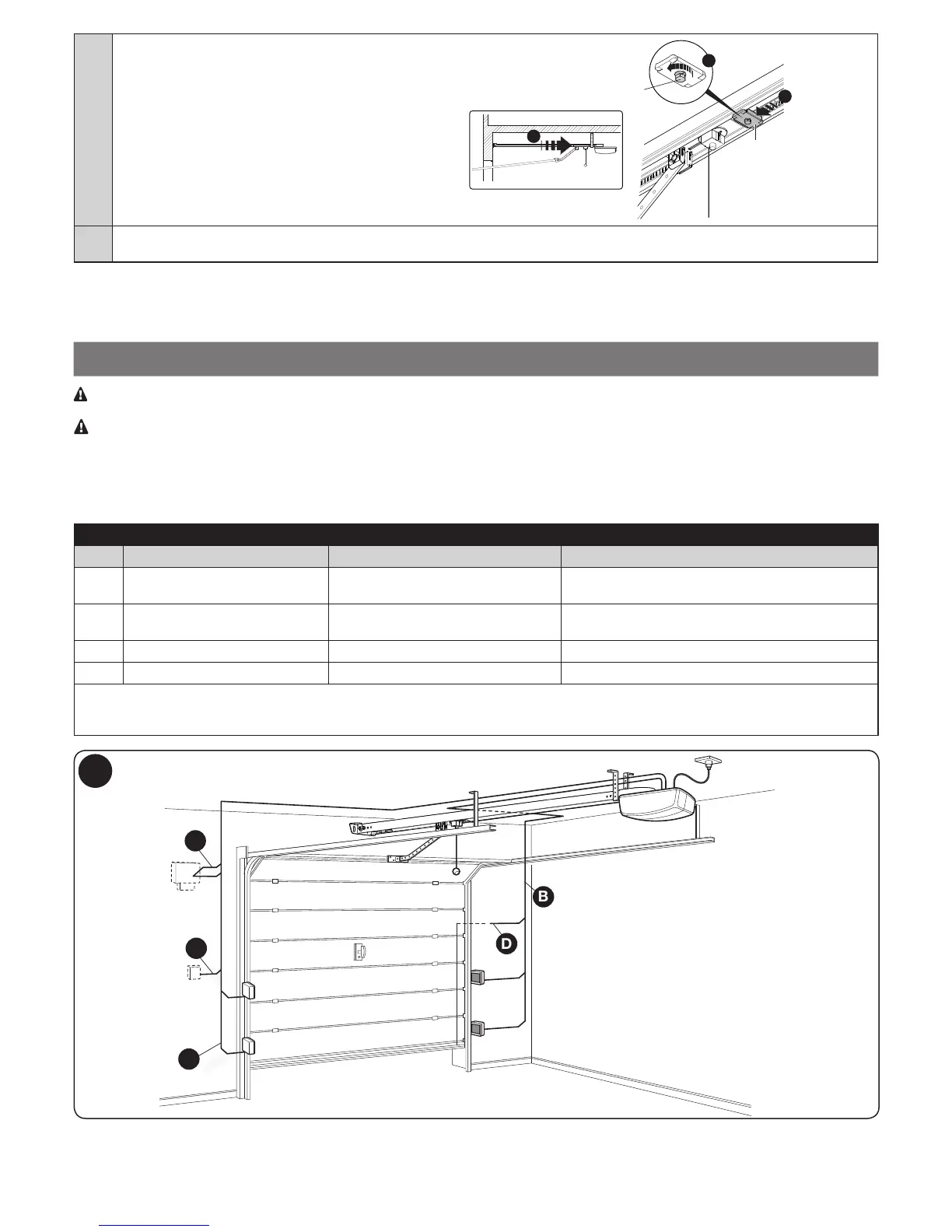
Fig. 7 shows the electrical connections in a typical installation; the adjacent diagram (step 02.) shows the connections to be made on the control
unit.
4.1 - Types of electrical cables
Table 5 - Types of electrical cables (see Fig. 6)
Connection Type of cable Maximum length
A FLASHING LIGHT
WITH ANTENNA
1 cable: 2 x 0.5 mm
2
1 type-RG58 shielded cable
20 m
20 m (recommended < 5 m)
B PHOTOCELLS 1 cable: 2 x 0.25 mm
2
(TX)
1 cable: 2 x 0.25 mm
2
(RX)
30 m
30 m
C KEY SELECTOR 2 cables: 2 x 0.5 mm
2
* 50 m
D PRIMARY SENSITIVE EDGES 1 cable: 2 x 0.5 mm
2
** 30 m
*
**
The two 2 x 0.5 mm
2
cables can be replaced by a single 4 x 0.5 mm
2
cable.
Special devices, which enable connection even when the leaf is moving, must be used to connect movable edges to sliding leaves.
6
A
B
B
C
D

 Loading...