26 – English
12
MAINTENANCE
To ensure constant safety levels a long service life, the system must be serviced regularly: at least every 6 months or after maximum 3,000
movements since the last service.
WARNING! – The maintenance operations must be performed in strict compliance with the safety directions provided in this
manual and according to applicable legislation and standards.
01.
Disconnect the power supply to the gearmotor and check the state of deterioration of all the automation’s constituent materials:
pay special attention to erosion and oxidation of structural components. Replace any parts that are not to standard
02. Check the state of wear of moving parts: the pinion and all parts of the door, and replace any worn components if necessary
03. Restore the power supply and run all the tests and checks indicated in Paragraph 6.1 - Testing
13
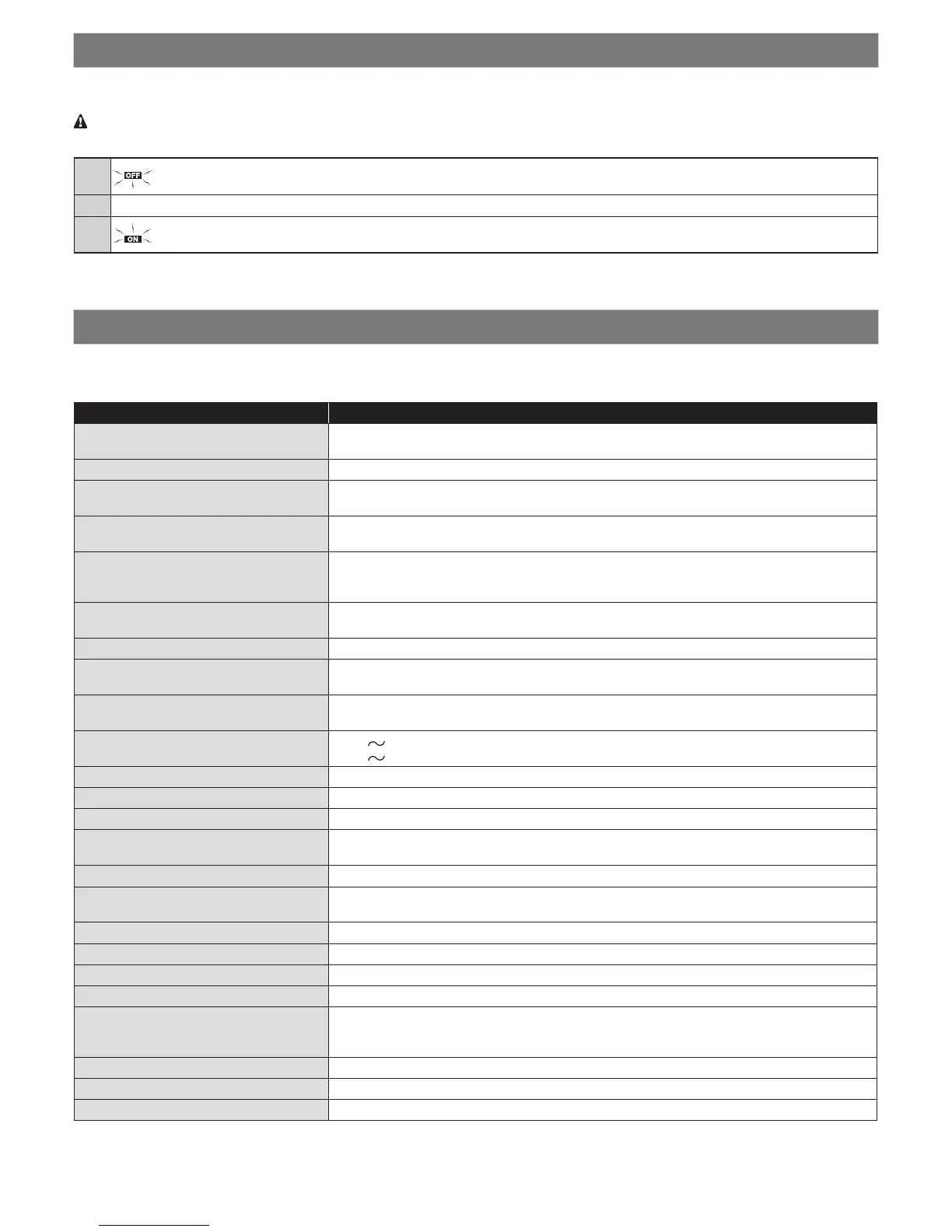
TECHNICAL SPECIFICATIONS
All technical specications stated herein refer to an ambient temperature of 20°C (± 5°C). • Nice S.p.A. reserves the right to modify its products
at any time when deemed necessary, while nonetheless maintaining their intended use and functionality.
SN6011
Product type Electromechanical gearmotor for the automatic movement of garage doors for residential use,
inclusive of electronic control unit
Pinion
Diameter 9.5 mm, 28 teeth; for SNA30 or SNA30C guides and guides supplied with SPIN10KCE
Peak torque (corresponding to the force re-
quired to move the door)
9.9 Nm
(550 N)
Nominal torque (corresponding to the force
required to keep the door moving)
4.95 Nm
(275 N)
No-load speed (corresponding if “Fast”
speed is programmed)
106 rpm
(0.20 m/s)
The control unit allows for programming 2 speeds equal to roughly 100%–60%
Nominal torque speed (corresponding if
“Fast” speed is programmed)
45 rpm
(0.08 m/s)
Maximum frequency of operating cycles 30 cycles per day (the control unit limits the cycles to the maximum shown in Tables 3 and 4)
Maximum continuous operating time 4 minutes (the control unit limits continuous operation to the maximum values given in Tables 3
and 4)
Application limits In general, SPIN is able to automate sectional or overhead doors that fall within the dimensions
stated in Table 2 and the limits specied in Tables 3 and 4
SPIN power supply
SPIN/V1 power supply
230 V (±10%) 50/60 Hz
120 V (±10%) 50/60 Hz
Maximum power input 200 W
Insulation class 1 (a safety earthing system is required)
Emergency power supply No
SPIN courtesy light
SPIN/V1 courtesy light
Internal LED courtesy light (tting not accessible to the user)
FLASH ashing light output for 1 ELDC ashing LED
STOP input For normally closed, normally open or 8.2 kΩ xed resistor contacts; with self-recognition (any
variation from the memorised status triggers the “STOP” command).
SbS input For normally open contacts (closing of the contact triggers the SbS command).
Radio ANTENNA input 52 Ω for RG58 or similar type cable
Radio receiver Incorporated
Programmable functions 6 ON-OFF and 6 adjustable functions
Self-recognition functions Self-recognition of the type of “STOP” device (NO or NC contact or 8.2 kΩ resistor)
Self-recognition of the door opening and closing positions and calculation of the
slowdown and partial opening points.
Operating temperature –20°C ... +55°C
Protection rating IP 40 (to be used only in indoor or protected environments)
Dimensions / weight 225 mm x 330 mm (h) x 100 mm / 3.3 kg

 Loading...