12 – English
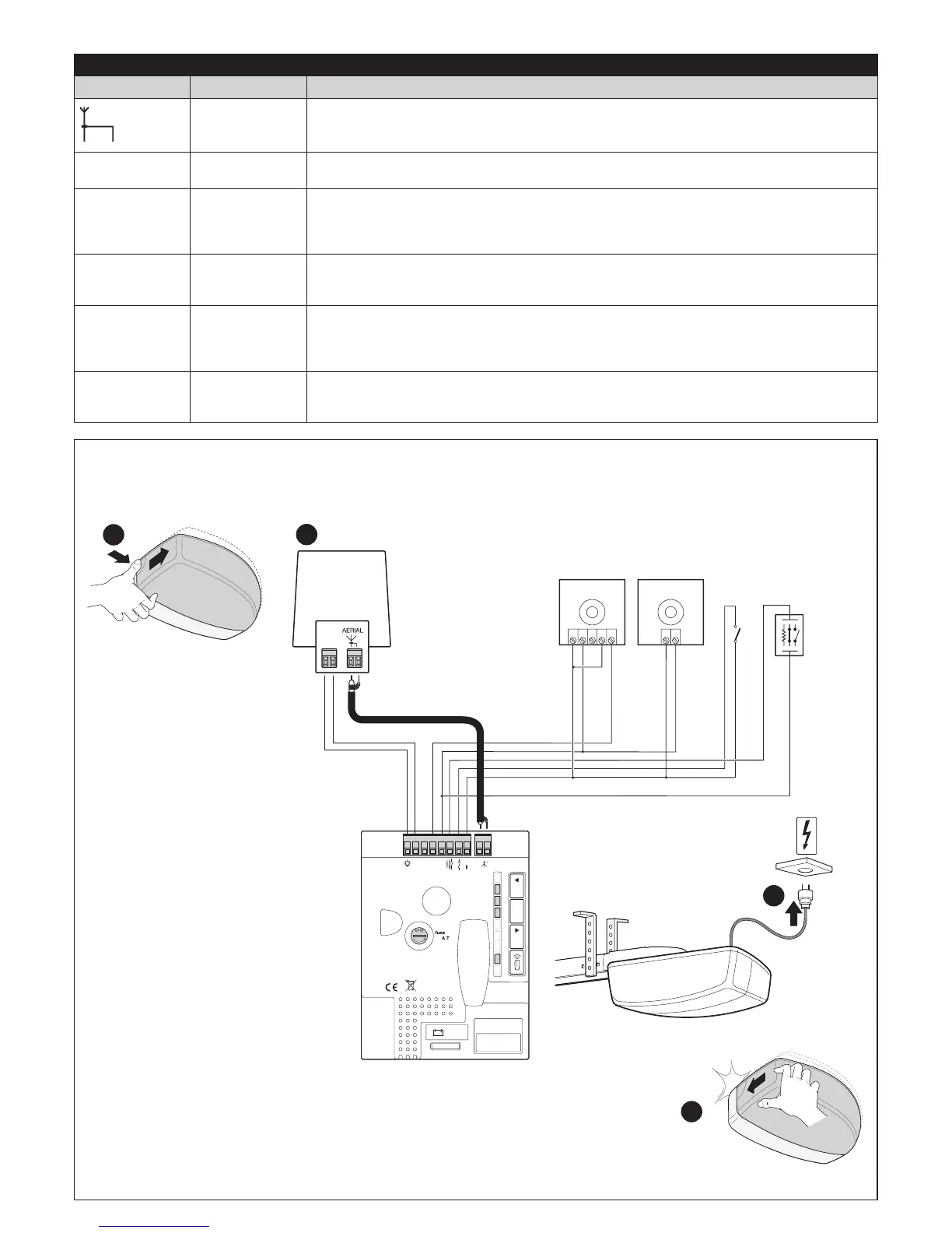
4.2 - Electrical cable connections
Table 6 - Description of the electrical connections (see diagram below)
Terminals Function Description
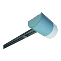
ANTENNA - connection input for the radio receiver antenna. The antenna is incorporated in the warning light;
alternatively, an external antenna can be used, or a section of wire already present on the terminal,
which functions as an antenna, can be left
1 - 2 SbS - input for devices that control the movement; it is possible to connect Normally Open (NO) devic-
es to this input
3 - 4 STOP - input for devices that block or even stop the current manoeuvre; Normally Closed (NC) contacts,
Normally Open (NO) contacts or 8.2 kΩ xed resistor devices can be connected by making special
arrangements on the input. For further information on the STOP function, see Paragraph 8.1 -
STOP input
1 - 5 PHOTO - input for safety devices such as photocells. They intervene during the closing phase, by reversing
the manoeuvre. Normally Closed (NC) contacts can be connected. For further information on the
PHOTO function, see Paragraph 8.1 - Photocells
4 - 6 PHOTOTEST - whenever a manoeuvre is begun, the relative safety devices are all checked and the manoeuvre
only starts if the test has a positive outcome. This can only be accomplished using a special type
of connections: the “TX” photocells are powered separately with respect to the “RX” receivers. For
further information on the connection, see Paragraph 8.1 - Photocells
7 - 8 FLASH - on this output it is possible to connect a Nice warning light (for the relevant models see Chapter
13 - Technical specications). During the manoeuvre the light ashes at intervals of 0.5 seconds on
and 0.5 seconds off.
1 - over the cover
2 - connect the electrical cables of the motor and accessories (depending on the control unit model)
3 - connect the power cable
4 - after completing the programming sequences, close the cover
1
NO
FLASH
2
Flash
87 65 43 21
Photo Test
Photo
GND
Stop
SbS
L1L2L3
R
24 V
Aerial
TX
230

 Loading...