22 – English
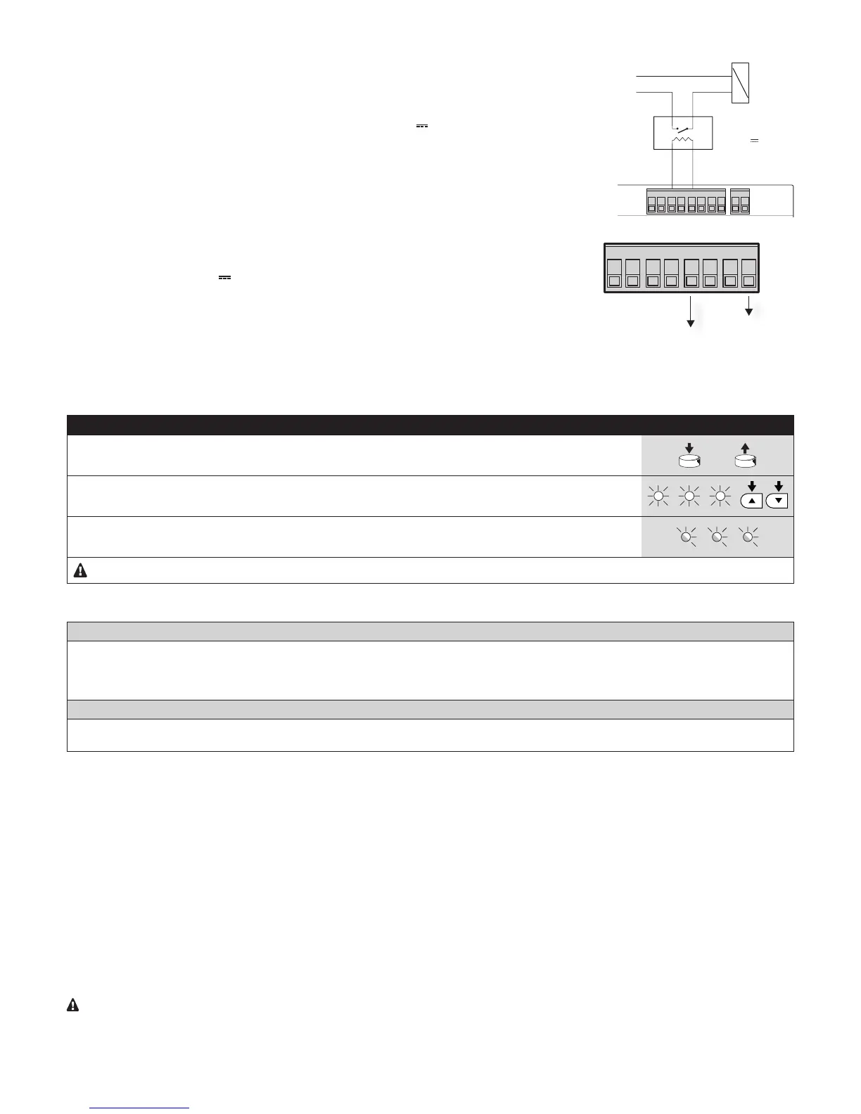
8.2 - Electric lock
The “phototest” output is active by default for the “phototest” function.
8 7 6 5 4 3 2 1
V Elettroserratura
12+230V
Elettroserratura
Relè
24V
Alternatively, the output can be programmed to control an electric lock. When the opening manoeu-
vre starts, the output is activated for 2 seconds; in this way an electric lock can be connected. The
output is not activated during the closing manoeuvre and, therefore, the electric lock must reset
mechanically.
The output cannot directly command the electric lock but only a 24V 2 W load.
The output must be interfaced with a relay, as shown in the adjacent gure.
8.3 - Connecting external devices
If the user needs to power external devices, such as a proximity reader for transponder cards or
the light for the key-operated selector, it is possible to tap power as shown in the adjacent gure.
87 65 43
The power is supplied at 24 V –30% to +50% with 100 mA maximum available current.
8.4 - Full deletion of the memory
When full deletion of the memory is required, to restore the default settings, perform the following procedure with the motor sta-
tionary:
Table 22 - Procedure for fully deleting the memory
01.
Press and hold the (arrow up) and (arrow down) keys simultaneously for 3 seconds.
3 s
02.
When all the LEDs light up simultaneously, release the keys.
03.
LEDs L1, L2 and L3 will start ashing at the end of the procedure.
After the Full Deletion the limit switch acquisition procedure can be started by pressing OPEN or CLOSE.
8.5 - Special functions
“Always open” function
This function is a control unit feature that enables the user to command an opening manoeuvre when the “Step-by-Step” command lasts
longer than 3 seconds. This is useful, for example, for connecting a timer contact to the “Step-by-Step” input in order to keep the door open
during a specic time bracket.
This feature is valid regardless of the “Step-by-Step” input programming (see the “Step-by-Step Function” parameter - Table 13).
“Move anyway” function
In the event that one of the safety devices is not functioning properly or is out of order, it is still possible to command and move the door in
“Man present” mode. For further details, refer to the “USER GUIDE” pull-out insert (nal part of the manual)
8.6 - Accessories
The following optional accessories are available:
• SPA2:
mechanical release device with metal cord. For use in systems that envisage only the automated door as a point of access.
• SPA5: oscillating arm. Required if the door to be automated is an overhead door with springs or counterweights.
8.7 -
Connecting the Oview programmer
It is possible to connect the Oview programming unit to the control unit, via the IBT4N interface through a bus cable with 4 electrical wires inside.
This unit enables quick and full programming of the functions, parameter adjustment, updating of the control unit rmware, diagnostics to detect
any malfunctions and periodic maintenance.
The Oview allows for operating on the control unit at a maximum distance of roughly 100 m. If several control units are networked with each
other in a BusT4 network, by connecting the Oview to one of them, it is possible to view on the display all the networked control units (up to a
maximum of 16 units).
The Oview unit can also be left connected to the control unit during normal operation of the automation, so that the user can send commands
using a specic menu.
Warning! - Before connecting the IBT4N interface, it is necessary to disconnect the control unit from the power supply.

 Loading...