English – 13
5
STARTING THE AUTOMATION AND CHECKING THE CONNECTIONS
5.1 - Connecting the automation to the mains electricity
To connect SPIN to the main electricity, simply insert the plug into a power outlet; if necessary, use a common adapter if the plug version is not
compatible the available socket.
Never cut or remove the cable supplied with SPIN. If it is not already available, the power socket for connecting SPIN must be
made by qualied and experienced personnel in strict observance of current legislation, standards and regulations. The power
supply line must be protected against short-circuits and ground leakage; a device must be provided to enable disconnection of
the power supply during the installation and maintenance of SPIN (the plug with outlet are suitable for this purpose).
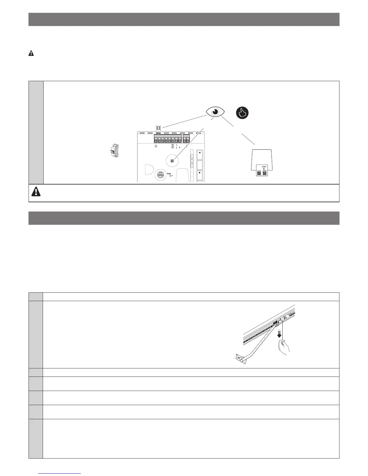
01. Proceed as described below:
• Make sure that the green “OK” LED ashes regularly, with one ash per second.
• Check that the motor does not control the movement of the door and that the ashing light and courtesy light are off.
ON
FLASH
OFF
2
Flash
8 7 6 5 4 3 2 1
Photo Test
Photo
GND
Stop
SbS
L1
L2
L3
24 V
Aerial
OpenStop/SetClose
OFF
If the above conditions are not satised, immediately switch off the power supply to the control unit and carefully check the electrical
connections. Additional useful information on troubleshooting can be found in Chapters 9 and 10.
6
TESTING AND COMMISSIONING
These are the most important phases in the automation’s arrangement to ensure maximum system safety.
They must be carried out by a qualied and expert technician who must dene the necessary tests to verify the solutions adopted to counter
any risks present, and check compliance with the laws, regulations and standards: in particular, with all the requirements of the EN 13241-1, EN
12445 and EN 12453 standards.
6.1 - Testing
Before running the testing procedure, it is rst necessary to have completed the “device acquisition” procedure (see Paragraph 7.2). The testing
procedure can also be performed as a periodic check of the automation devices. Each component of the system (sensitive edges, photocells,
emergency stop, etc.) requires a specic testing phase; for these devices, observe the procedures given in the respective instruction manuals.
Run the SPIN test as follows:
01. Check that all provisions stated in the “General warnings” chapter have been strictly observed.
02. Release the door by pulling the release cord and verify whether it
can be moved manually in both the opening and closing directions
with a force no greater than 225 N.
03. Put the motor carriage back.
04. Using the key-operated selector or the transmitter or the control unit buttons, test the opening and closing of the garage door and make
sure that it moves in the intended direction.
05. Perform the test several times to verify that the door moves smoothly, that there are no points of excessive friction and that there are no
defects in the assembly or adjustment.
06. Check the proper operation of all the safety devices, one by one (photocells, safety edges, etc.). In particular, whenever a device is
activated, the green OK LED on the control unit emits 2 faster ashes to conrm that the control unit has recognised the event.
07. Check the operation of the photocells and any interference with other devices:
1 - insert a cylinder with 5 cm diameter and 30 cm length across the line of sight, rst near the TX then near the RX
2 - check that the photocells intervene in any case, switching from the active status to the alarm status and vice-versa
3 - check that their intervention determines the intended response of the control unit: for example, that it causes the movement to invert
during the closing manoeuvre.

 Loading...