English – 5
1
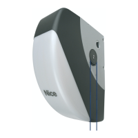
PRODUCT DESCRIPTION AND INTENDED USE
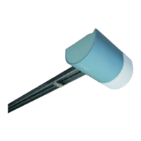
SPIN is a range of gearmotors designed for automating sectional doors and – in combination with accessory SPA5 (supplied separately) – pro-
truding or non-protruding spring or counterweight overhead doors.
SPIN operates using electric power. In the event of a power failure, the gearmotor can be released in order to move the door manually.
WARNING! – Any use other than that specied herein or in environmental conditions other than those stated in this manual is
to be considered improper and is strictly forbidden!
Table 1 - Description of the SPIN components
Model Gearmotor Guide Radio receiver Radio transmitter
SPIN10KCER10 SN6011 3 x 1 m Incorporated FLO2R-S*
SPIN11KCER10 SN6011 3 m Incorporated FLO2R-S*
* See Paragraph 7.4 for the types of transmitters that can be used.
2
APPLICATION LIMITS
The data relative to the performances of SPIN range products appear in Chapter 13 (“Technical specications”) and are the only values that allow
for determining whether the products are suitable for the intended application.
The structural characteristics of the SPIN products make them suitable for use on sectional and overhead doors within the limits shown in Tables
2, 3 and 4.
Table 2 - SPIN gearmotor operating limits
Model Sectional doors Non-protruding overhead
doors (with accessory SPA5)
Protruding overhead doors
(with accessory SPA5)
or spring overhead doors
(without SPA5)
width height width height width height
SPIN10KCER10 3.7 m 2.4 m 3.5 m 2.2 m 3.5 m 2.8 m
SPIN11KCER10 3.7 m 2.4 m 3.5 m 2.2 m 3.5 m 2.8 m
Warning! Any other use or use with dimensions greater than those specied is considered non-conforming. Nice declines all
liability for damage and injury resulting from non-conforming use.
The measurements shown in Table 2 are purely indicative and are used for a general estimate only. The actual suitability of SPIN for automating
a specic door depends on the degree of door leaf balancing, guide friction and other aspects, including occasional circumstances such as wind
pressure or the presence of ice, which could obstruct the door’s movement.
To determine the actual conditions, the force required to move the leaf throughout its path must be measured, to ensure that this value does not
exceed the “rated torque” specied in Chapter 13 (“Technical specications”); moreover, to calculate the number of cycles/hour and consecutive
cycles, it is important to consider the data shown in Tables 3 and 4.
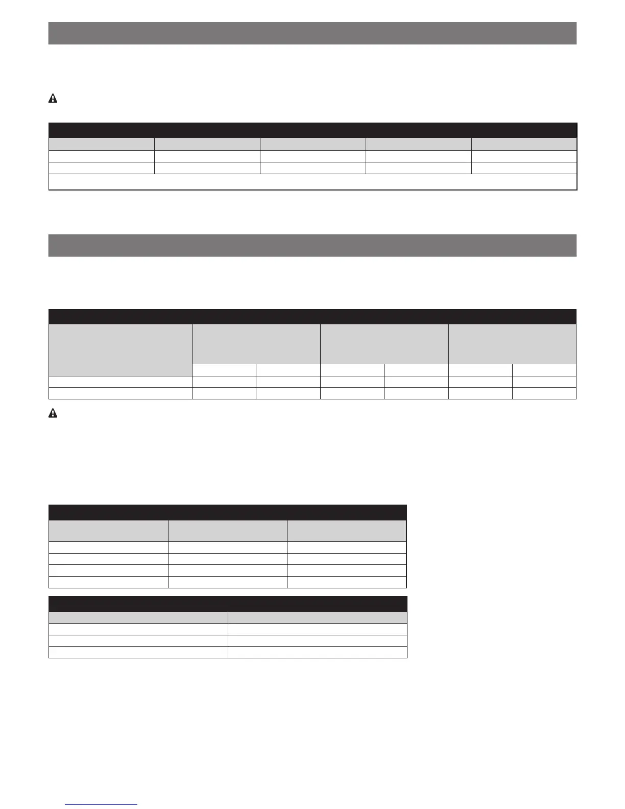
Table 3 - Limits relating to the door leaf height
Leaf height (metres) Maximum no. of cycles/
hour
Maximum no. of consecu-
tive cycles
Up to 2 16 8
2 – 2.5 12 6
2.5 – 3 10 5
3 – 3.5 8 4
Table 4 - Limits relating to the force required to move the door leaf
Force required to move the leaf (N) SN6011 cycle reduction percentage
Up to 200 100 %
200 – 300 70 %
300 – 400 25 %
The height of the door allows for calculating the maximum number of cycles per hour and consecutive cycles, while the force required to move
the door allows for determining the cycle reduction percentage; for example, for a leaf that is 2.2 m high 12 cycles/hour and 6 consecutive
cycles can be completed, but if a force of 250 N is required, these gures would have to be reduced to 70%, that is, 8 cycles/hour and roughly
4 consecutive cycles.
To avoid overheating, the control unit has a limiter that operates on the basis of the motor’s effort and duration of the cycles, and intervenes
when the maximum limit is exceeded.
Note: 1 kg = 9.81 N (example: 500 N = 51 kg)

 Loading...