English – 21
8
FURTHER INFORMATION
8.1 - Adding or removing devices
It is possible to add or remove devices at any time; in particular, various types
of devices can be connected to the STOP input, as described in the following
paragraphs; for the relevant procedure see Paragraph 7.3 (“Acquisition of the
opening and closing positions”).
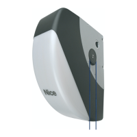
PHOTO
0 V
24 V
FLASH
12V 21W
PHOTOTEST/
ELET. BLOCK
GND
STOP
SbS
AERIAL
87654 3 21
The adjacent gure shows the wiring diagram for connecting the various de-
vices.
STOP input
This input stops the movement immediately, followed by a brief reversion. Devices with output featuring normally open Normally Open (NO)
contact, Normally Closed (NC) contact, as well as devices with 8.2 kΩ xed resistor output (sensitive edges), can be connected to this input.
The control unit recognises the type of device connected to the STOP input during the acquisition phase (Paragraph 7.3); subsequently, a
STOP command is triggered whenever the device detects any difference from the acquired setting. Multiple devices – even of different types
can be connected to the input:
- Any number of NO devices can be connected in parallel.
- Any number of NC devices can be connected in series.
- Multiple NC devices can be “cascade” connected with a single 8.2 kΩ terminating resistor.
- It is possible to create the NO and NC combination by connecting two NO contacts in parallel, but the NC contact must be connected in
series to an 8.2 kΩ resistor.
If the STOP input is used to connect devices with safety functions, only the devices with 8.2 kΩ xed resistor guarantee Category 3 safety
against faults, in accordance with the EN 13849-1 standard.
Photocells
The control unit features a “Phototest” function which increases the reliability of the safety devices, enabling it to be classied in Category 2 in
accordance with the EN 13849-1 standard regarding the combination of the control unit and safety photocells.
Each time a manoeuvre is started, all safety devices involved are checked and only if everything operates correctly will the manoeuvre be
started.
Should the test fail (photocell blinded by the sun, cables short-circuited, etc.), the fault is identied and the manoeuvre is disabled.
To add a pair of photocells, connected them as described below:
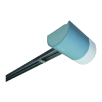
• Connection without “Phototest” function:
Power the receivers directly from the control unit’s device output
(terminals 1 - 4).
230V
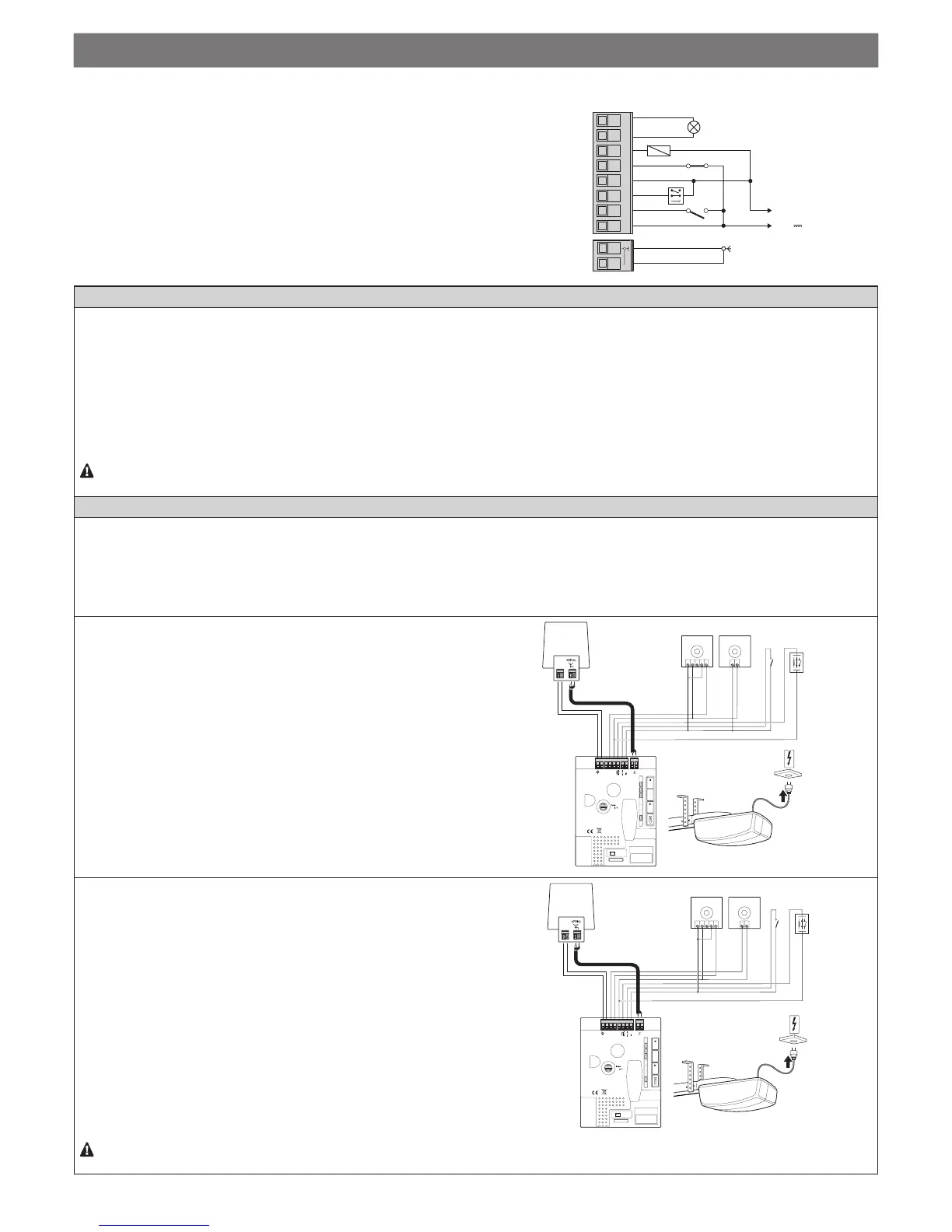
• Connection with “Phototest” function:
The receiver power comes directly from the services output (ter-
minals 1 - 4), while that of the transmitters is from the “Phototest”
output (terminals 4 – 6). The maximum admissible current on the
“Phototest” output is 100 mA.

 Loading...