Installation
3-3
Part 1073401_07
E 2021 Nordson Corporation
Installation Requirements
Before installing the melter, ensure that the desired installation location
provides the required clearances, environmental conditions, and utilities.
Clearances
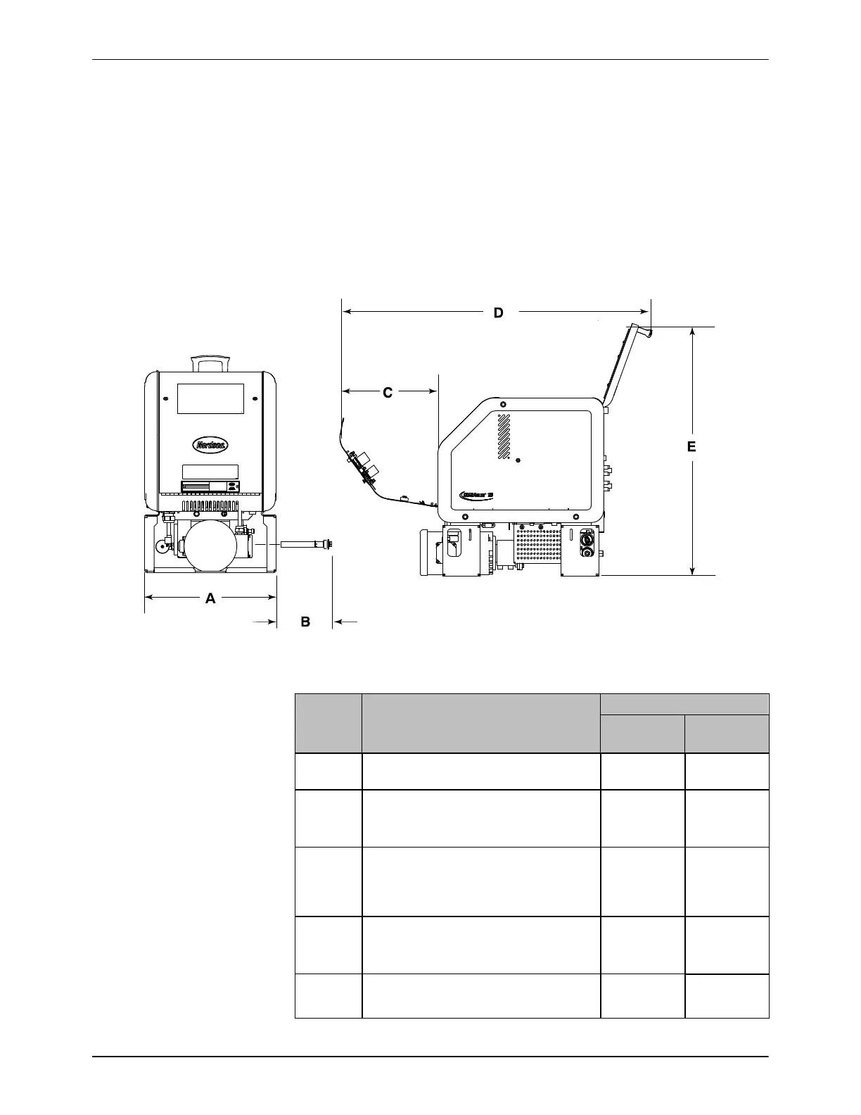
Figure 3‐1 illustrates the minimum clearances that are required between the
melter and surrounding objects. Table 3‐1 describes each clearance.
Figure 3-1 Minimum installation clearances
Table 3-1 Minimum Installation Clearances
Item Description
Required Clearance
D10L
D16L
D4L
A
Width of melter at the outside of the mounting
brackets.
393 mm
(15.48 in.)
334 mm
(13.14 in.)
B
Clearance required between the melter and
the nearest object in order to remove the
filter.
203 mm
(8.00 in.)
203 mm
(8.00 in.)
C
Clearance required between the front end of
the melter (control panel) and the nearest
object in order to fully open the electrical
enclosure door
330 mm
(12.99 in.)
281 mm
(11.05 in.)
D
Minimum horizontal space required for the
melter when both the electrical enclosure
door and tank lid are fully opened.
1052 mm
(41.40 in.)
900 mm
(35.42 in.)
E
Minimum vertical space required for the
melter when the tank lid is at its highest point.
878 mm
(34.57 in.)
640 mm
(25.18 in.)

 Loading...


