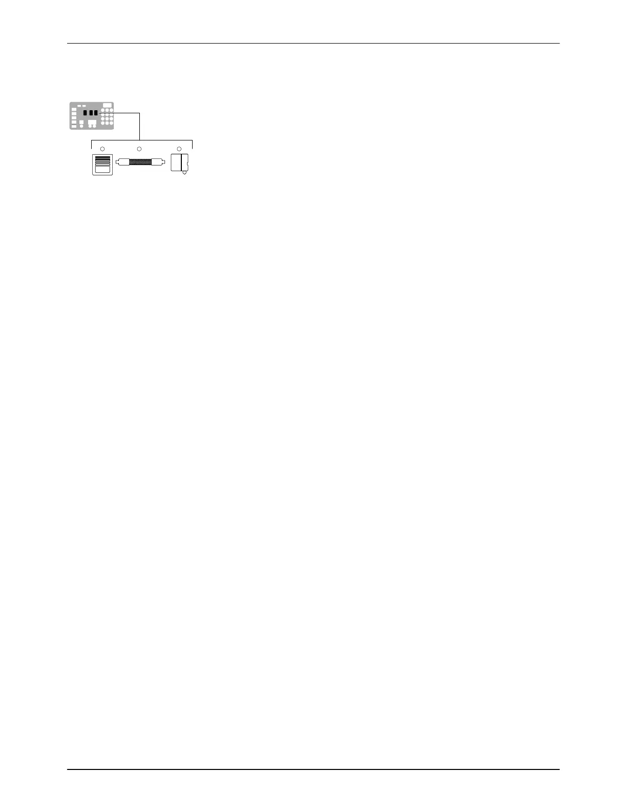
Component keys
(tank, hose, and applicator)
Operation
4-2
Part 1073401_07
E 2021 Nordson Corporation
More about Heated Components
The melter contains three groups of heated components. These are the tank
group, which contains the tank and the pump, the hose group, and the
applicator group. Component groups are represented on the control panel by
the component keys shown to the left.
Heated components within each group are identified by their position
number. The position of the tank and pump is fixed at 1. Hose and applicator
position numbers are automatically assigned based on the hose/applicator
receptacle they are connected to. For example, the position numbers of a
hose/applicator pair that is connected to the second receptacle would be
hose position 2 and applicator position 2.
NOTE: In some installations, auxiliary devices (such as a heated air
manifold) may be connected to a hose/applicator receptacle. In such cases,
you should label (or otherwise identify) the auxiliary device as to the hose or
applicator position number that represents the device. The control panel will
identify such devices as a hose or applicator, regardless of what the device
actually is.

 Loading...


