Troubleshooting
6-7
Part 1073401_07
E 2021 Nordson Corporation
Returning the Melter Setup to Factory Settings
By returning the melter to its factory setting many common melter problems
can be isolated to either a problem with the melter settings or the melter
hardware.
To return the melter to its factory settings, simultaneously press and hold the
Setup key and the right‐display DOWN arrow key, and then, while holding
down these keys, cycle the melter control switch off and on. When the melter
restarts, release the two keys.
Identifying Electrical Components
Tables 6‐3 through 6‐4 provide detailed descriptions of the circuit board
indicators, connection points, and test points that are referred to in the
troubleshooting chart. Figure 6‐1 illustrates the location of each of these
circuit board components.
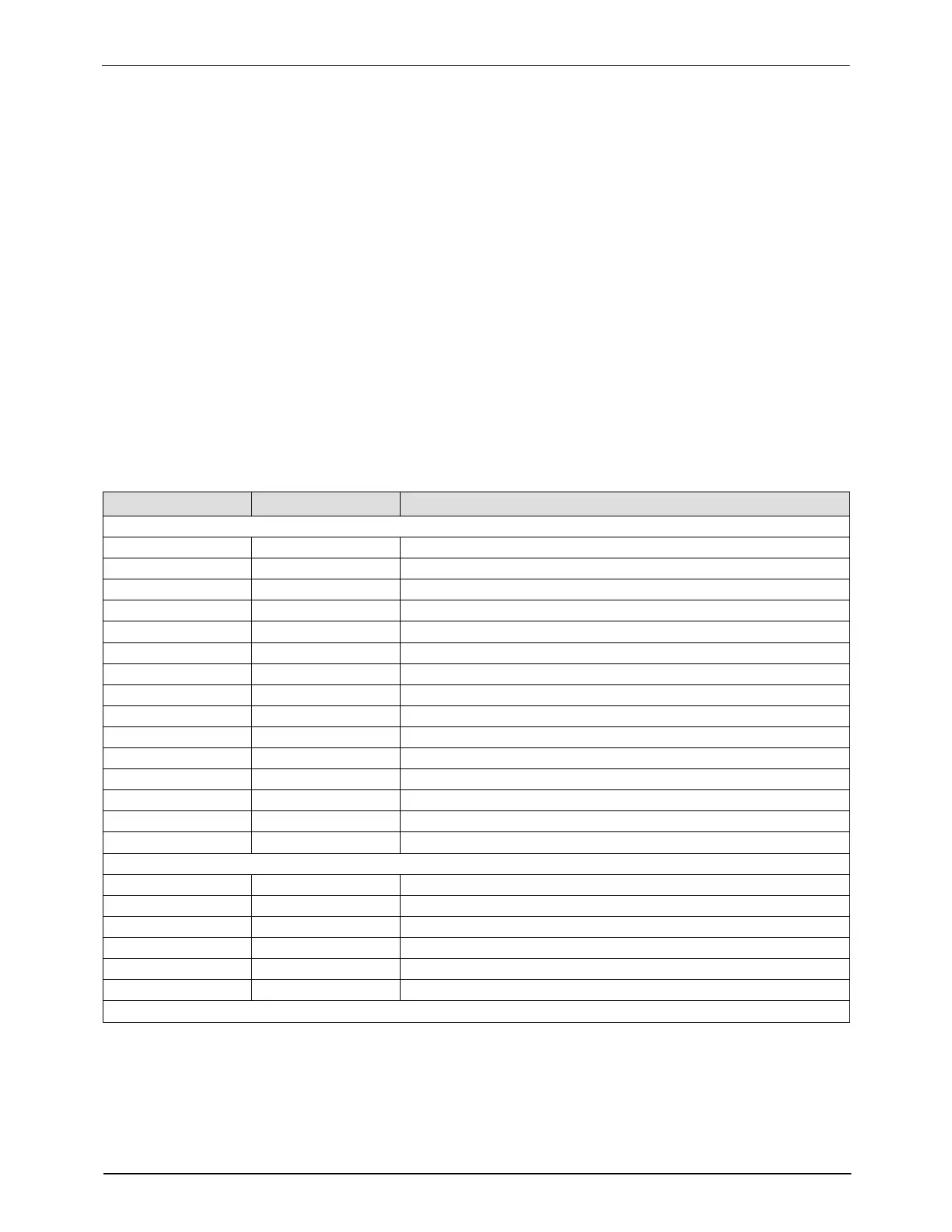
Table 6-3 Main Board Components
Item Number Type Description
Indicators
DS2 Neon Power to tank heaters
DS3 Neon Power to pump heater
DS4 Neon Power into board
DS5 Neon Power to hose/applicator 1 heaters
DS6 Neon Power to hose/applicator 2 heaters
DS7t Neon Power to motor
DS8 LED Control signal for hose 1
DS9 LED Control signal for applicator 1
DS10 LED Control signal for tank heaters
DS11 LED Control signal for motor
DS12 LED Control signal for applicator 2
DS13 LED Control signal for hose 2
DS14 LED Control signal for pump heater
DS15 LED +5 VDC out of low-voltage power supply
DS17 LED Trigger closure present at XP3 or XP4
Fuses
F1/F2 −− Tank heaters (10 A, 250 V, fast-acting)
F3/F4 −− Main power to board (2A, 250 V, slow-blow)
F5/F6 −− Pump heater (5 A, 250 V, fast-acting, 5 x 20 mm)
F7/F8 −− Hose/applicator 1 heaters (6.3 A, 250 V, 5 x 20 mm)
F9/F10 −− Hose/applicator 2 heaters (6.3 A, 250 V, 5 x 20 mm)
F11/F12 −− Motor power (6.3 A, 250 V, 5 x 20 mm)
Continued...

 Loading...


