NFS2-3030 Operations Manual — P/N 52546:N1 06/20//2014 35
Pre-alarm Event Operation of the Control Panel
2.3.4 Interpreting Type ID Codes
The Type ID code that displays in a point trouble message is related to the type and function of the
point that initiates the trouble. For example, a monitor module with a
PULL STATION Type ID code
means that the monitor module connects to a manual pull station. If the Type ID code is unfamiliar,
refer to Appendix A, “Software Type ID Codes”, on page 78. This appendix is an alphabetical list
of Type ID codes and an explanation of each.
2.4 Pre-alarm Event
The Pre-alarm function is used to receive an early warning of potential or incipient fire conditions.
The Pre-alarm function provides one of two settings as follows:
• Alert – a non-latching setting that causes a Pre-alarm when a detector reaches its programmed
Pre-alarm sensitivity threshold. Non-latching means the condition will automatically restore to
normal once the detector’s obscuration readings drop below its Pre-alarm threshold.
• Action – a latching setting that causes a Pre-alarm when a detector reaches its programmed
Pre-alarm level. Latching means the condition will not restore itself to normal once the
detector’s obscuration readings drop below its Pre-alarm threshold. The panel must be reset.
Alert and Action settings are set individually with detector point programming. Individual detector
sensitivity threshold settings can have a value of one through nine, and are set by the programmer.
A sensitivity threshold setting of zero indicates the detector does not participate in prealarm.
For more detailed information on Pre-alarm, refer to this panel’s programming manual.
2.4.1 How the Control Panel Indicates a Pre-alarm
When a detector activates a Pre-alarm, the control panel does the following if there are no higher
priority unacknowledged events:
• Pulses the panel sounder (if the piezo is enabled)
• Flashes the
PRE-ALARM LED
•Displays
PREALARM in the upper left corner of the LCD, as well as the sensitivity reading, the
type code and other information specific to the detector as shown in Figure 2.5.
• Sends a Pre-alarm message to the History buffer, installed printer and annunciators.
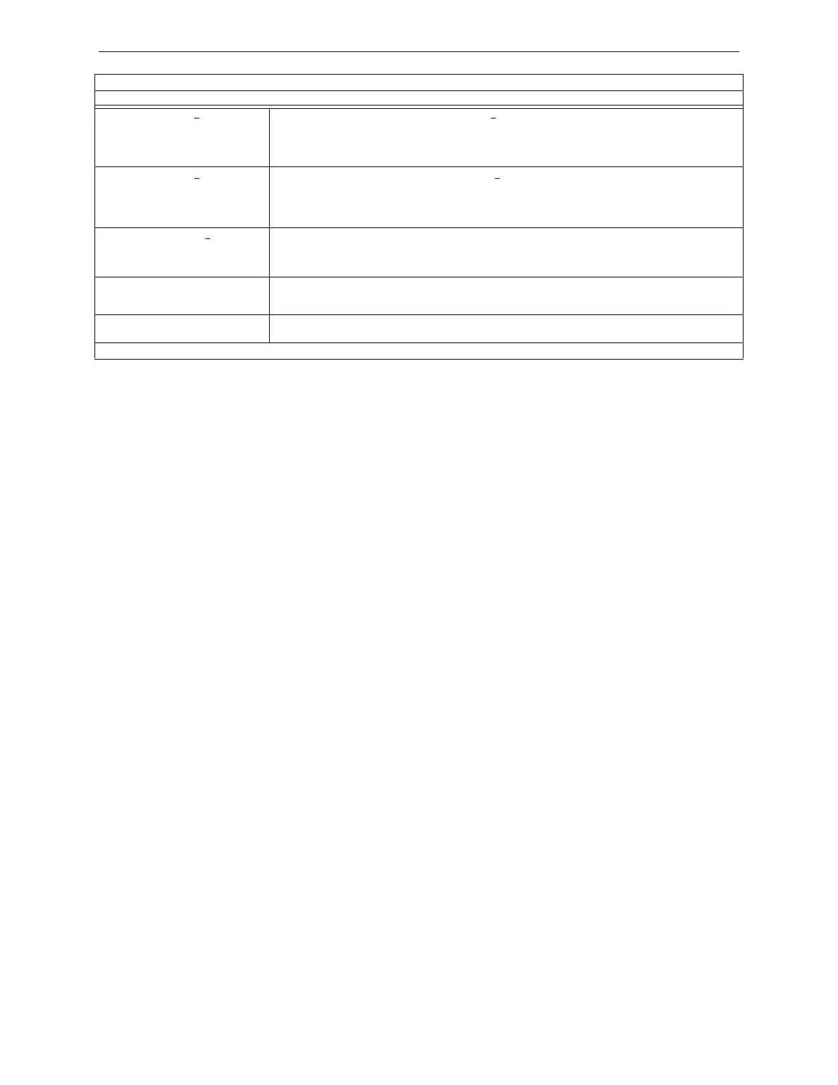
STYLE 6 POS. LOOP x There is an open circuit on the positive side of loop x. Style 6 and Style 7 are supervised methods of
communicating with addressable devices. If the control panel detects a trouble (open), it will drive both ends of
the loop, maintaining communication in an unsupervised method. The latching trouble will display on the panel
as a Style 6 trouble until you correct the condition and press reset. Style 7 configuration of the SLC requires the
use of isolator modules & bases.
STYLE 6 NEG. LOOP x
There is an open circuit on the negative side of loop x. Style 6 and Style 7 are supervised methods of
communicating with addressable devices. If the control panel detects a trouble (open), it will drive both ends of
the loop, maintaining communication in an unsupervised method. The latching trouble will display on the panel
as a Style 6 trouble until you correct the condition and press reset. Style 7 configuration of the SLC requires the
use of isolator modules & bases.
STYLE 6 SHORT LOOP x
Style 6 and Style 7 are supervised methods of communicating with addressable devices. If the control panel
detects a trouble (short), it will drive both ends of the loop, maintaining communication in an unsupervised
method. The latching trouble will display on the panel as a Style 6 trouble until you correct the condition and
press reset. Style 7 configuration of the SLC requires the use of isolator modules & bases.
SYSTEM INITIALIZATION One or more devices (detectors or modules) can not report activation. This can occur following system startup,
when exiting Walk Test, following an autoprogram, or following a device trouble of No Response. Will clear
when all un-initialized devices are initialized.
VESDA TROUBLE A trouble has occurred on a VESDA node. Possible troubles may include: Communication failure on the
VESDA detector loop, incompatible VESDA software versions, or a VESDA configuration error.
* This trouble may be fire panel or backup battery related. Test and replace backup batteries if necessary.
SYSTEM TROUBLES
TROUBLE MESSAGE TYPE TROUBLE DESCRIPTION
Table 2.2 System Troubles (4 of 4)

 Loading...


