NFS2-3030 Operations Manual — P/N 52546:N1 06/20//2014 83
How Releasing Zones Operate Releasing Zones
B.2 How Releasing Zones Operate
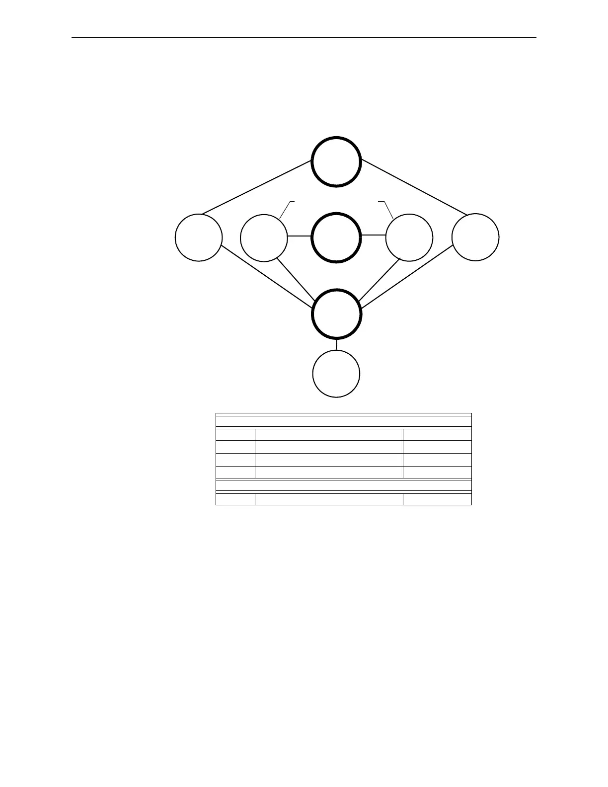
The figure below contains an illustrated example of how Releasing Zones work, using cross zone
selections with four detectors and an NAC mapped to Releasing Zone 1 (listed as ZR01 in the zone
map). Table B.2 on page 84 lists the cross zone selections and the conditions that activate the
Releasing Zone:
Figure B.1 Illustrated Example of Cross Zone Programming
Listing of each Cross Zone option and the conditions required to activate the Releasing Zone,
according to the example shown in Figure B.1 on page 83.
Releasing
Zone ZR01
General
Zone Z002
General
Zone Z001
Smoke
Detector
L02D101
Smoke
Detector
L02D103
Heat
Detector
L02D104
Smoke
Detector
L02D102
SLC
NAC
Zone map = Z002 ZR1
Zone map = Z001 ZR01
Zone map = Z001 ZR01
INPUTS ZONE MAP
L02D101 Smoke Detector Z001, ZR01
L02D102 Smoke Detector Z001, ZR01
L02D103 Smoke Detector Z002, ZR01
L02D104 Heat Detector Z002, ZR01
OUTPUT
SLC Module Releasing Circuit ZR01

 Loading...


