5-21
5 Operation
CJ-series PROFIBUS Master Unit Operation Manual for NJ-series CPU Unit (W509)
5-4 Configuring the Master
5
5-4-4 Configuring CX-Server
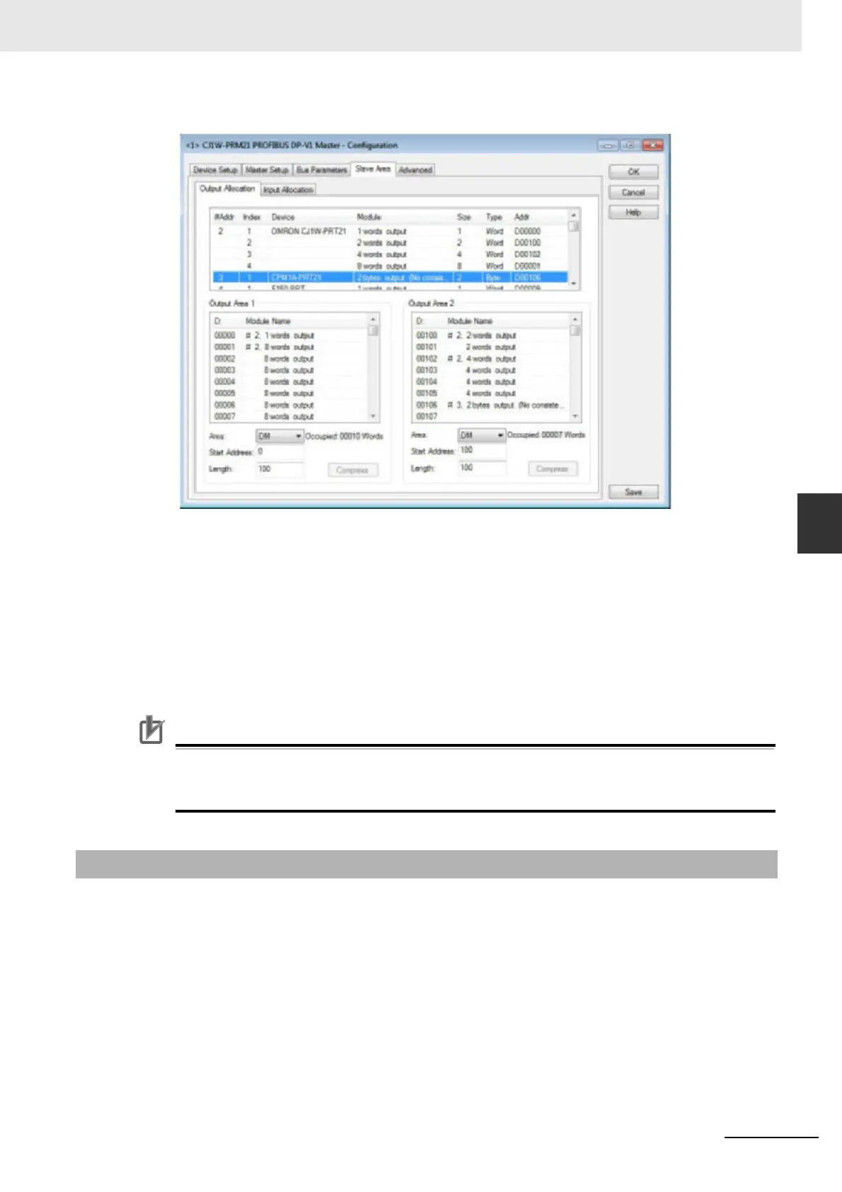
By default all Output data is mapped on to Output Area 1 and all Input data is mapped on to Input Area
1. Each of these Areas can be mapped on to CPU memory independently of each other.
Changing the mapping can be achieved using drag & drop. The module which is mapped to Area 1 and
which must be mapped to Area 2, can be copied there by dragging it from the overall module list on top
to Area 2.
The I/O mapping concept is discussed in section 5-5-2 Mapping I/O Data.
Note 1 By default the Auto-Addressing option will be enabled (see section 5-4-1 Setting the Mas-
ter Parameters). If any I/O modules are moved from one Area to another, the I/O modules
in first Area are re-mapped to close all the gaps between mappings.
Precautions for Correct UsePrecautions for Correct Use
When mapping the I/O Areas, make sure that the I/O data will not overlap the Unit’s own CIO
Area or one or more of the I/O data areas of any other CPU or I/O Unit. The CJ1W-PRM21 Mas-
ter DTM does not check this. Failure to avoid this, will lead to unpredictable behavior of the Unit.
Configuring Communication
The CJ1W-PRM21 Master DTM uses CX-Server to connect to the Unit for downloading a configura-
tion as well as monitoring the Master Unit. To setup the communication to the Unit, perform the fol-
lowing procedure.
1
Open the CJ1W-PRM21 Master DTM Configuration Interface, Device Setup tab.
2
Make sure that the Unit Number has been set to the unit number set on the PROFIBUS Master
Unit, through the rotary switch on the front.
3
Select the Configure button to start CX-Server.
5-4-4 Configuring CX-Server

 Loading...


