EasyManua.ls Logo

Omron CJ Series User Manual

Omron CJ Series
304 pages
To Next Page IconTo Next Page
To Previous Page IconTo Previous Page
Page #287 background imageLoading...
Page #287 background image
A-21
Appendices
CJ-series PROFIBUS Master Unit Operation Manual for NJ-series CPU Unit (W509)
A-6 I/O Data Type Definitions
App
A-6 I/O Data Type Definitions
Standard PROFIBUS DP defines two types of I/O data.
8-bit bytes sized data.
16-bit word sized data.
The standard for PROFIBUS extension, also referred to as PROFIBUS DP-V1, defines the following
additional data types:
8-bit byte signed / unsigned Integer data.
16-bit word signed / unsigned Integer data.
32-bit double word signed / unsigned Integer data.
32-bit single precision floating point (IEEE754 format).
ASCII Text strings of indeterminate length (in 8-bit bytes).
7 byte Date format.
6 byte Time of Day format.
6 byte Time Difference format.
The NJ-series controller unit defines similar data types, which however differ in size and/or storage for-
mat in the CPU memory. Since the PROFIBUS Master Units provides an interface between a PROFI-
BUS network and the NJ-series controller unit, the Unit will provide the necessary conversions to
ensure that the I/O data on the PROFIBUS network is transferred to the CPU memory in the correct for-
mat. This Appendix explains the conversions in detail.
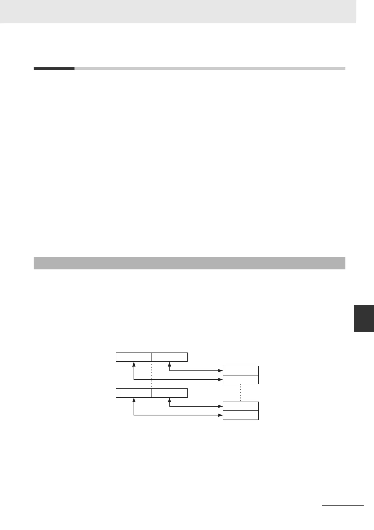
8-bit Byte Data
The NJ-series controller unit memory layout is word oriented. The PROFIBUS Master will therefore
convert a stream consisting of one or more bytes of data into words. The figure below shows the
conversion in graphic format.
Note m = (n-1)/2, rounded to the next lowest integer.
A sequence of bytes transmitted over the PROFIBUS network is copied to the CPU memory in the
following procedure.
The first two bytes are stored in the lowest word of the destination data block in CPU memory
word. Every consecutive two bytes are stored in the next higher words.
Odd byte numbers are copied to the Least Significant byte of a CPU memory word.
Even byte numbers are copied to the Most Significant Byte of a CPU memory word.
A-6-1 Integer Data Conversions
CPU Data area
Byte
sequence
Byte 1
Byte 2
PROFIBUS
Bit 07 Bit 00
Byte n-1Byte nWord m
Bit 15 Bit 00
Byte 1Byte 2Word 0
Byte n-1
Byte n

Table of Contents

Other manuals for Omron CJ Series

Questions and Answers:

Omron CJ Series Specifications

General IconGeneral
Programming LanguageLadder Diagram (LD), Function Block Diagram (FBD), Structured Text (ST), Sequential Function Chart (SFC), Instruction List (IL)
I/O CapacityVaries by model (e.g., up to 2560 I/O points)
Communication PortsEthernet, RS-232, RS-485, USB
Power Supply100-240V AC or 24V DC
MountingDIN rail
CPU TypeVaries by CPU unit
Data MemoryVaries by CPU unit
Expansion CapabilitySupports expansion units and modules
Operating Temperature0°C to 55°C
Humidity Range10% to 90% (non-condensing)
DimensionsVaries by model (e.g., 90mm x 31mm x 90mm)
WeightVaries by unit type
Memory CapacityVaries by CPU unit; up to 800K steps
Program CapacityVaries by CPU unit; up to 800K steps

Summary

Features and System Configuration

PROFIBUS Master Unit

Details the features, services, and specifications of the PROFIBUS Master Unit.

Nomenclature and Installation

Configuration Software

CX-ConfiguratorFDT

Introduces CX-ConfiguratorFDT, its main window, functions, and device catalogue.

CJ1W-PRM21 PROFIBUS Master DTM

Details the configuration and diagnostic user interfaces for the CJ1W-PRM21 Master DTM.

Data Exchange with the CPU Unit

Device Variables for CJ-series Unit (Software Switches, Statuses)

Lists and explains device variables for CJ-series Units used for software switches and statuses.

Operation

Configuring the Slave Devices

Details the process of configuring slave devices, including I/O, parameters, and group assignment.

Configuring the Master

Explains how to configure the CJ1W-PRM21 Master DTM, including address and bus parameters.

Operating the Network

Describes how to control the network, change modes, and use global-control commands.

Message Communications

Acyclic Messages

Details specific acyclic message commands like EXPLICIT MESSAGE SEND and MEMORY AREA READ.

Troubleshooting and Maintenance

Troubleshooting with the PROFIBUS Master Unit Indicators

Guides troubleshooting using front panel indicators for unit startup and operational errors.

Troubleshooting Using Error Status

Explains how to troubleshoot using device variables for Unit and Master Errors.

Troubleshooting the Network

Covers troubleshooting for parameter downloads, network issues, and I/O communication.

Related product manuals